RonA
Active member
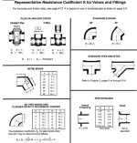
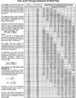
Just curious if anyone has calculated loss of flow from the bends in our turbo plumbing. This cast piece is a sharp 90deg that starts out at 3" id on the flange end and transitions to 2.690" id on the small end. If I cut it off and weld on a piece that it 3" id and blend it, it will still have to go down to about 2 3/4" id at the intercooler. Better to go larger all the way to the intercooler so it becomes the first restriction, or does it matter?
Thanks.
RonA
Thanks.
RonA
Attachments

Last edited: