This is to show how a delivery valve holder operates.
All measurments are + or - .002"
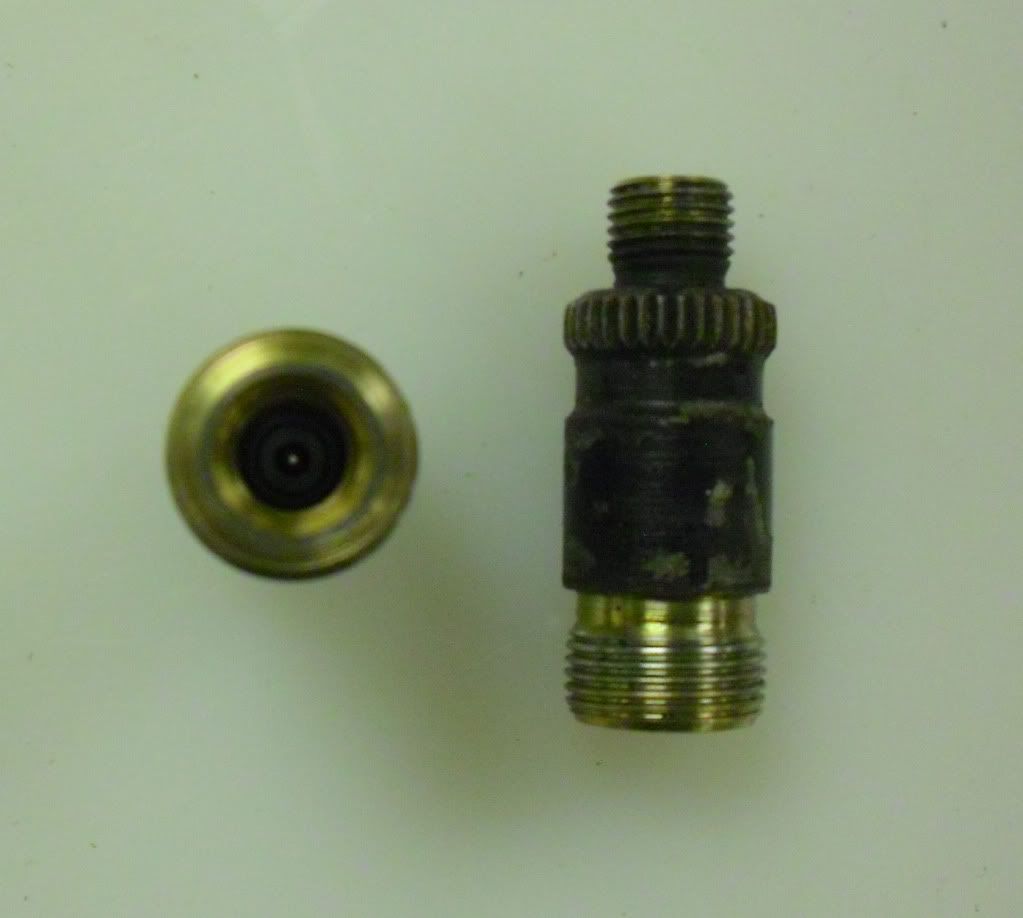
Unmodified holder, looks like the opening is too small to push fuel through untill you separate the parts.

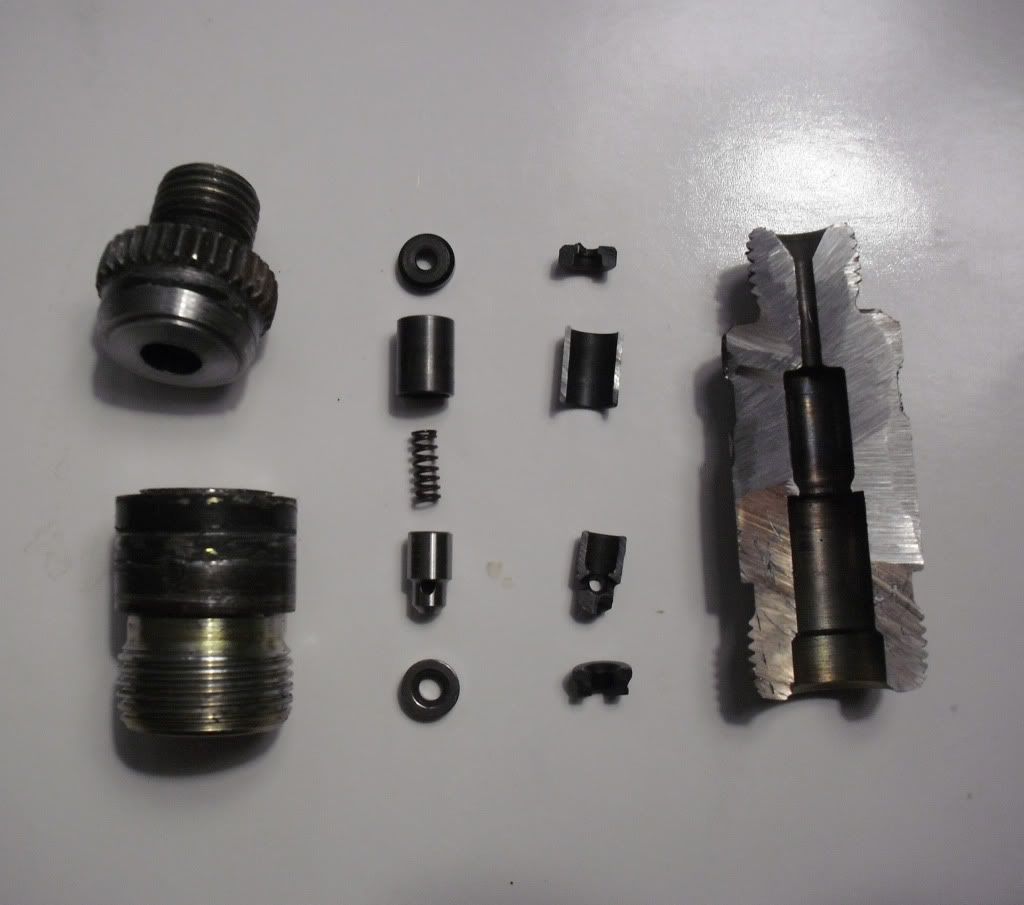
Holder on left split horizontally and parts pulled out. Holder on right everything is cut in half (missing spring on right).

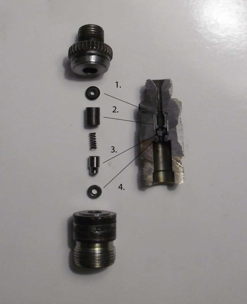
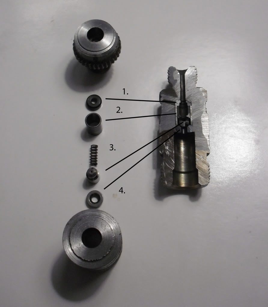
Sorry, but I dont know all the "officail" names of these parts, so I just used 1-4.
Parts assembled.
The fuel is first pushed up through #4 which has an opening of .120". It then is pushed up onto #3. #3 has a small .025" hole that goes straight through. This is the hole that most look at and think all the fuel is pushed through this small opening. That is a false assumption. The fuel pushes up on #3 and lifts it up off its seat on #4. #3 then has three holes for the fuel to pass through that are each .075" in diameter. The fuel then passes through the rest of #3 including through the spring. #3 moves up and down in #2 which is essentially just a sleeve. Next the fuel is pushed throught #1 which has a .100" diameter. Lastly the fuel is pushed through the rest of the holder which also has a .100" diameter.
As you can see the biggest resriction is the .100" passage. This design provides plenty of flow and thus does not need to be drilled out or have larger holders machined out.

another angle
