bateman
Active member
After a couple years on the shelf I got my B&M gated shifter installed. After taking a test drive I realize lockup is not happening. (1k ohm resistor in temp sensor, stock TPS and PCM) possibly a random problem showing it’s face after the shifter but I’ve checked everything. Only thing that I changed was removing the stock shift lever and replacing it with one for the cable. TV lever and adjustment did not change.
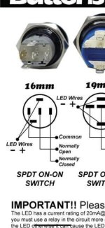
Moving on, I decide to go ahead and wire the Billet Automotive Buttons up that are installed in the shifter. They are lit with an LED when activated. My question is very basic and I assume I will be called a retard which is fine ha.
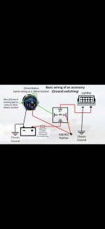
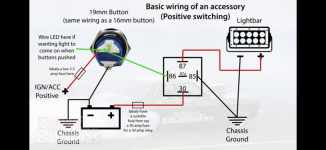
Trans is a 47RH (94-95). Can I wire these buttons up like so? Three wire plug on trans. Middle is power in. Outside wires are too ground for L/U and O/D. Can I put the switch on the ground wire with the LED wired on the same circuit. My thinking is there is always 12v going in, then I ground it to activate L/U or O/D and the circuit is completed for the light as well?
I ask this because I read something about a light back feeding to the PCM or something and I can’t understand how. Maybe that was for incandescent bulbs?
I understand this may not fix my problem. Could be a lock up solenoid failure or broken wiring harness. Just curious about the wiring for the switches as that will tell me if I have other issues. Right now I’m going to hope it’s the TPS.
Moving on, I decide to go ahead and wire the Billet Automotive Buttons up that are installed in the shifter. They are lit with an LED when activated. My question is very basic and I assume I will be called a retard which is fine ha.
Trans is a 47RH (94-95). Can I wire these buttons up like so? Three wire plug on trans. Middle is power in. Outside wires are too ground for L/U and O/D. Can I put the switch on the ground wire with the LED wired on the same circuit. My thinking is there is always 12v going in, then I ground it to activate L/U or O/D and the circuit is completed for the light as well?
I ask this because I read something about a light back feeding to the PCM or something and I can’t understand how. Maybe that was for incandescent bulbs?
I understand this may not fix my problem. Could be a lock up solenoid failure or broken wiring harness. Just curious about the wiring for the switches as that will tell me if I have other issues. Right now I’m going to hope it’s the TPS.