New Pro Stock Diesel build - 2 D Max

What should Michael name his new truck?

  • 2-D-Max

    Votes: 40 60.6%
  • 2wD-Max

    Votes: 7 10.6%
  • Something else (please post ideas)

    Votes: 19 28.8%

  • Total voters
    66
Mitch,
I have no idea where it was built, other than that it came from Texas and was raced for at least one season there around 2000. For sub-8.50 certification a chassis has to have a manufacturer's tag with a date and serial number on it, this chassis had no such tag. I was originally torn as to what I would put on a tag since I was just modifying the chassis, but now I'm down to just using one or two tubes from the original, so I have no qualms about calling it "mine" as far as the builder.

As the chassis certification tech pointed out, the tubing bends look like they were done on a very cheap bender. I would guess that two different people did the welding on it, one person was good but lazy (did not weld all the way around many tubes, but the portion they did weld looked good), while the other person wasn't as good. They also used some cheezy components like the Datsun struts, and the bed mounts were over 2" offset (the bed was mounted VERY crooked). I wouldn't be surprised if the build was started by one guy, then sold to another guy who finished it, who then sold it because it was an evil handling SOB.
 
Episode 11
NOTE: Due to the limitations on the number of photos I can post on many forums, I will post a more detailed version with more photos on the newly updated ISSPRO Website:
Please check it out over there!


Sorry for the lull in updates. Usually the gatherings of my extended family occur at my dad's house, but he was on a 3-month cruise with my aunt and uncle, so it fell to me to host those kind of gatherings. I hadn't done much housekeeping since hurting my back in December, as any "spare" time was spent on the race truck. I had LOTS of housecleaning to do before the Easter gathering. After that I went into prep mode for a child custody hearing. My attorney lets me do most of the prep work for trial so it costs me less money, but it means a significant amount of time. Immediately after that was our family Mother's Day gathering. Somewhere in there I de-winterized my gasser race car and my daughter's Jr Dragster, as we finally got in a local race without raining out.

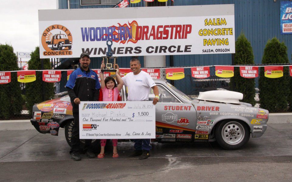
We traveled down to Redding, CA for the Jefferson State Diesel Nationals, where I went to the 3rd round in my dually, and lost with a decent light while running on my dial-in, as the other guy had an even better light and ran on HIS dial-in!

Two weeks later we headed to Mission, BC for the BD Diesel Nationals. That race was a little less successful, as I red-lit by 0.008, and managed to do it to someone who forgot to put his truck in 4x4 and cut a 0.476 light and ran 2+ seconds off his dial-in. It was a little less painful to lose the good race in Redding!

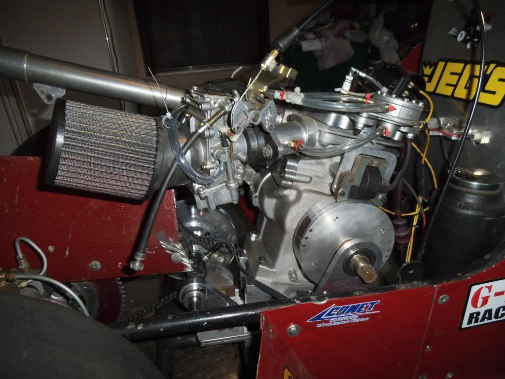
In my Vega I have been sorting out some issues, after doing some datalogging I figured out that one source of inconsistency was my torque converter.

Hughes-converter.jpg


After replacing it with a custom built unit from Hughes Performance, I won two races in a row, then took 2nd in the consolation bracket the next week (went out first round of the regular class when the other guy had a 0.008 light and ran 0.010 off his dial, while I cut a horrible light partially due to sun glare). Note to self - when everyone is lining up in the right lane, walk around the corner and see if the sun is glaring in the eyes of the left lane racers!

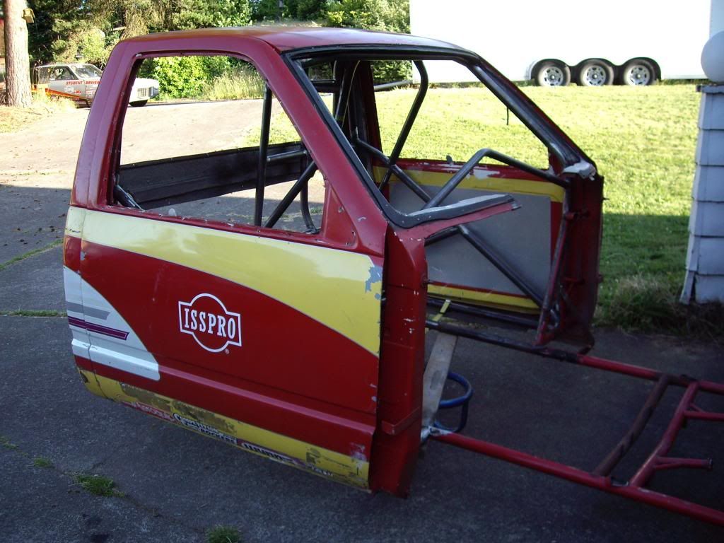
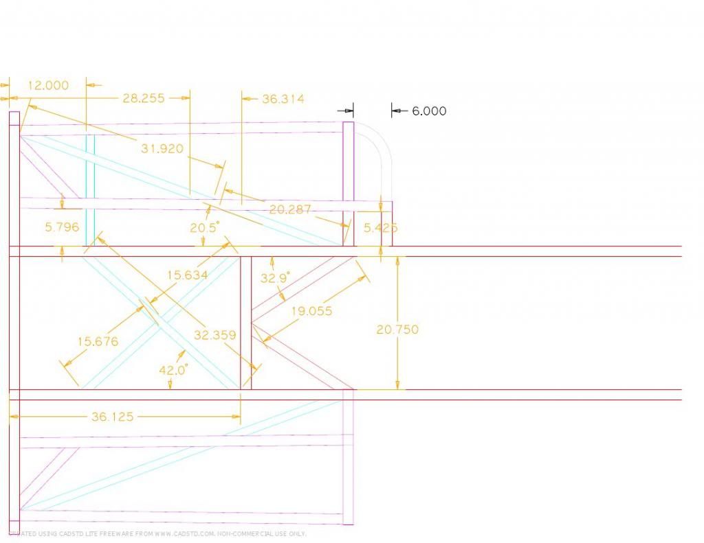
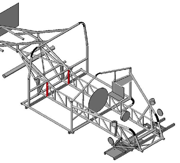
I updated the rendering of the truck to represent the altered wheelbase. I wanted to see how goofy it looks. I'm a bit biased but I kinda like it!

2DMax04d1.png


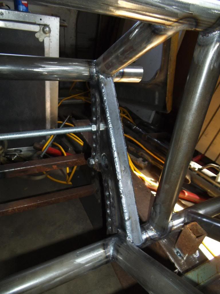
Despite the aforementioned items taking up my time, I still managed to keep working steadily (if not slowly) on the race truck. As we last left off I was basically starting the chassis over. With the help of my friend Duane Merritt and his chassis shop, we bent up some new bars. It was nice to start from scratch and make a few changes in the design of the chassis. A key part was the way the main hoop ties into the floor area and main crossmember. With this change I could get less likelihood of the main hoop collapsing, without resorting to gussets which can cause a stress concentration.

Just to help understand some of the decisions I have made on this chassis, here is a quick Structural Engineering 101:
When it comes to structural strength, bigger is NOT always better. In many cases you can make a part STRONGER (able to carry more load without failure) by REMOVING material. As counter-intuitive as this sounds, let me see if I can explain in a way that makes sense.

Metal fails when the load causes a stress level beyond its limit at that specific location. If a bar is undergoing a bending load, that bar will deflect proportinally to the load. However, if one section of that bar is "reinforced" such that it has much less deflection, the section adjacent to it will have substantially MORE localized deflection than without that reinforcement, as it is now the weak point with higher stress. This extra deflection is effectively a "stress riser", or a spot with increased stress, and a likely point of failure. If you remove some of that reinforcement such that the whole bar "distributes" the deflection evenly, the peak stress level will decrease. Basically you want to avoid drastic changes in cross section.

To save you from going back a few pages, this is what the main hoop used to look like:

New-7B-wide.jpg


With the old layout the main hoop did not tie directly to the outermost frame rails, so I would have needed extra tubes running there, forming a joint that is not as strong as it could be, and with some stress concentrations.

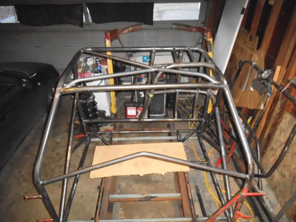
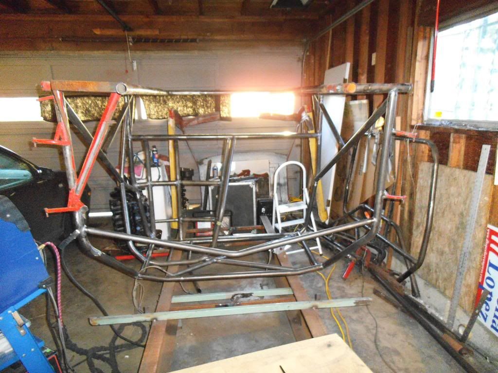
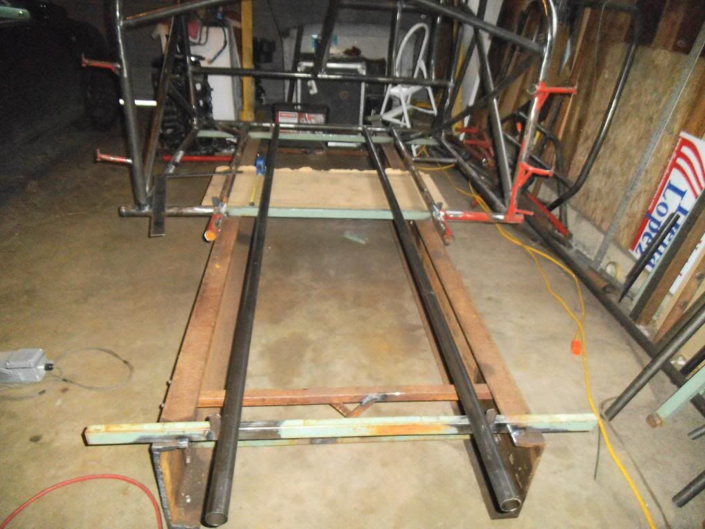
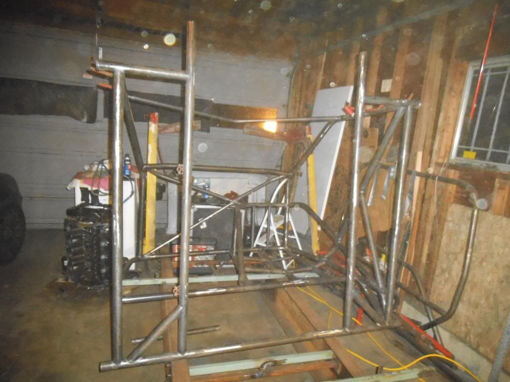
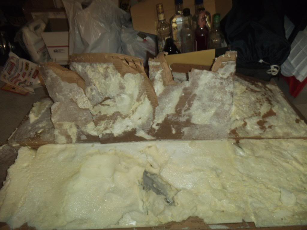
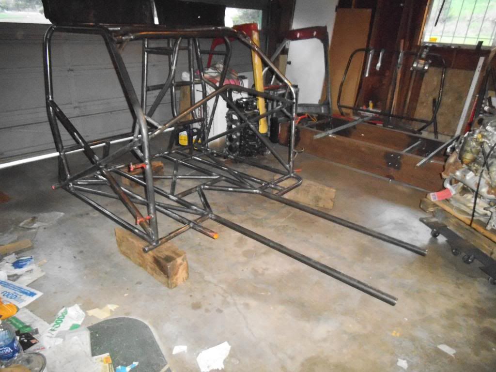
I removed the old main hoop and the right side roof/pillar bar, leaving almost nothing of the original chassis (and even more of that in the photo will be removed by the time this is completed). I left a lot of the floor in place so I had something to stand on when welding towards the top!


Front-removed-rear-vw.jpg


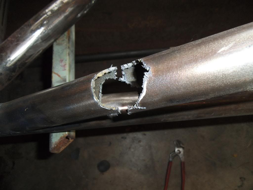
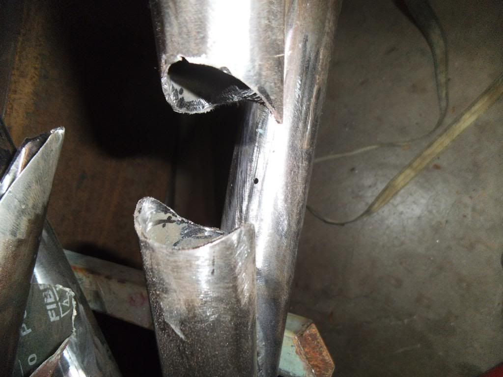
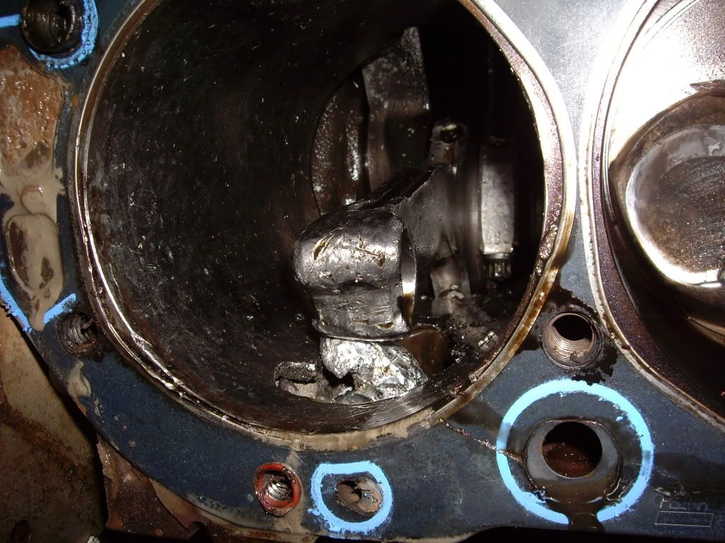
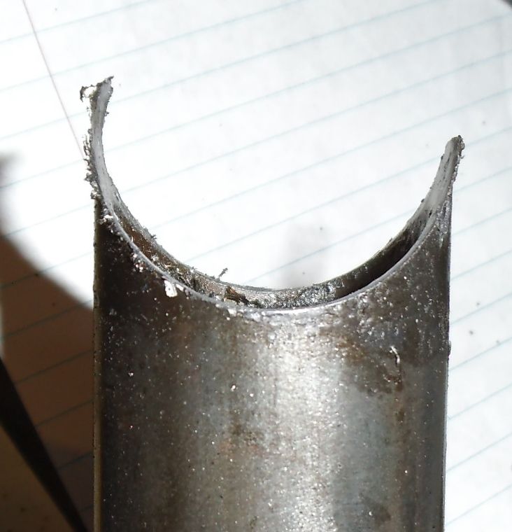
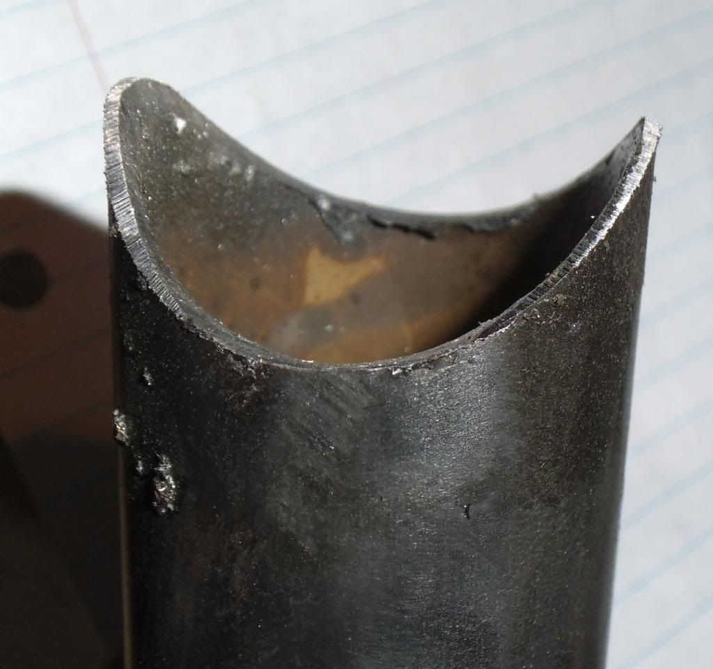
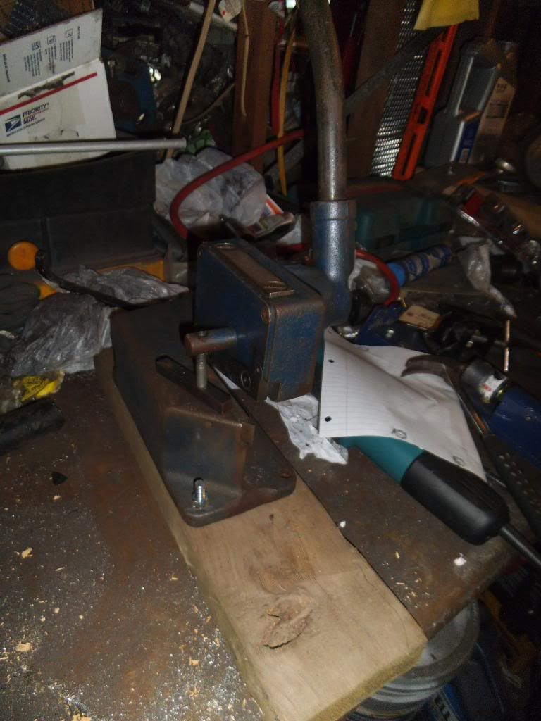
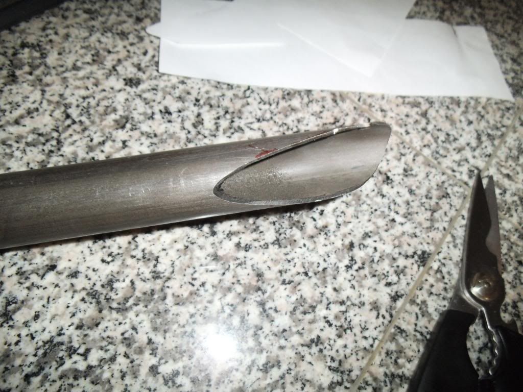
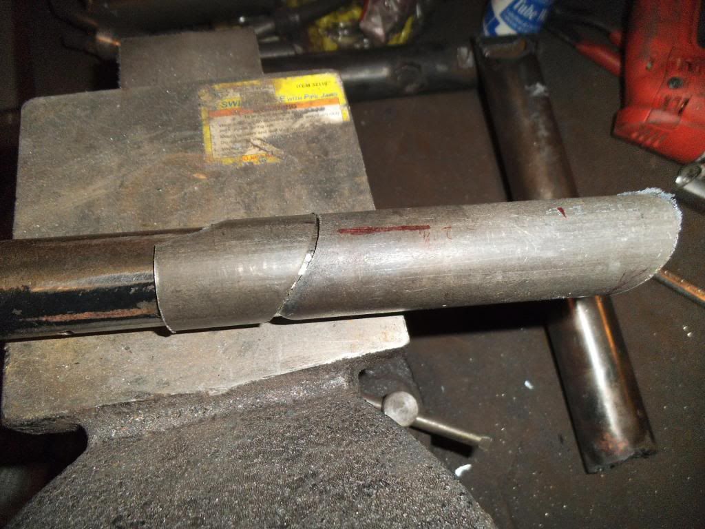
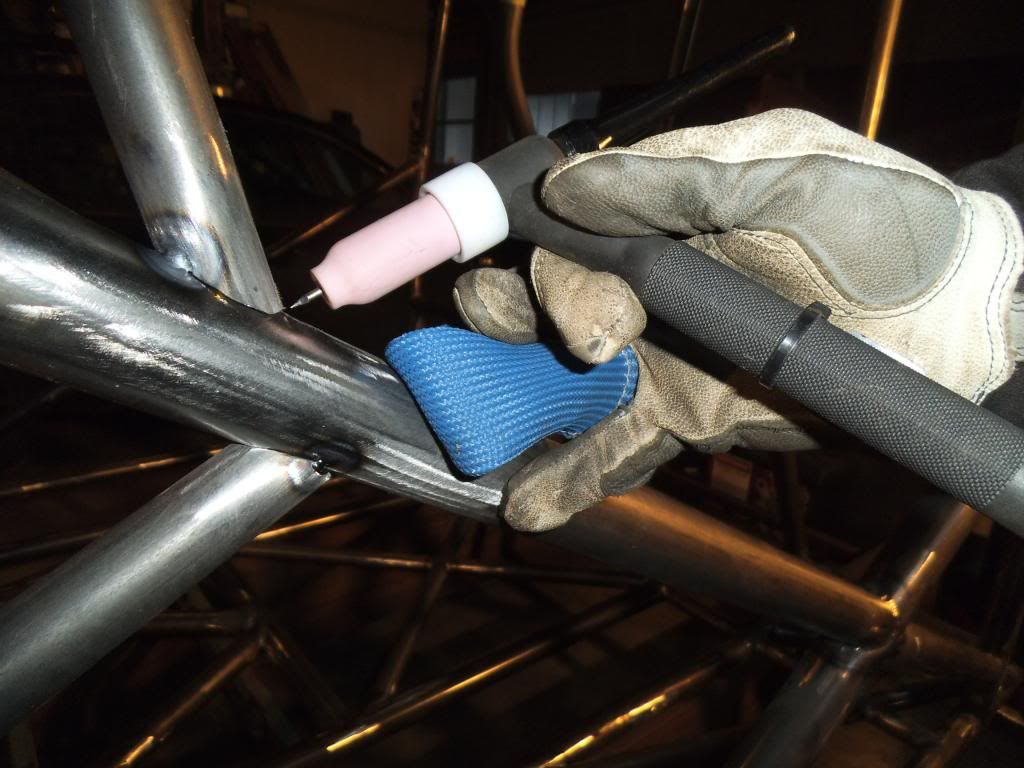
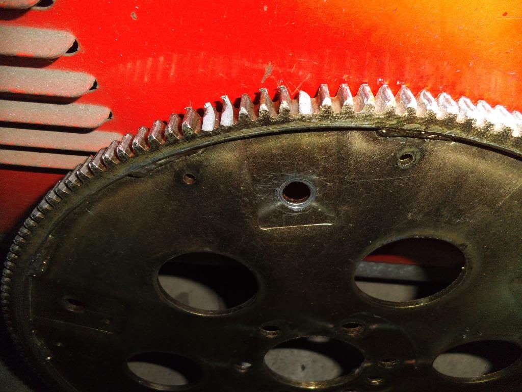
Now a quick tip - when using a tubing notcher, be damn sure that A) the tubing is well secured, and B) the hole saw shaft support is close to the saw itself, so flex does not allow it to move significantly. Here is a shot of me violating both of those rules, trying to cut at an angle the notcher would not otherwise work on:
Notcher-bad-angle.jpg


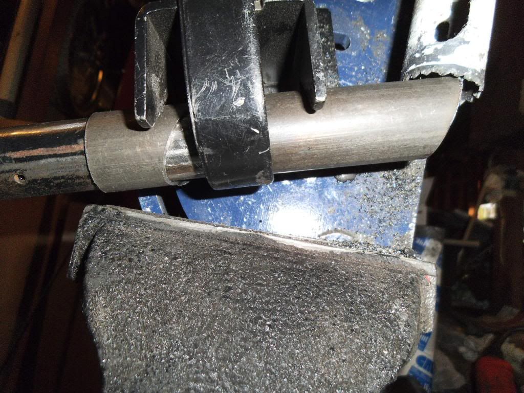
And this was the result:
Notcher-broken-teeth.jpg


Yup, those teeth did not survive the rocking of the hole saw!

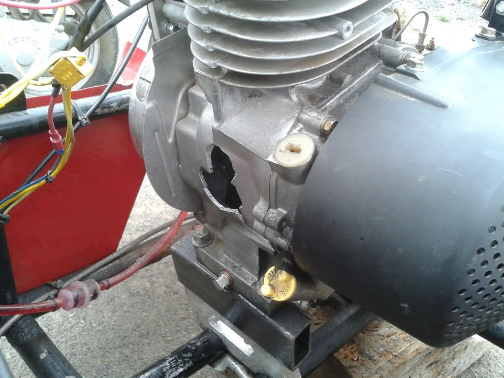
I am on my 3rd hole saw, the 1st 2 lasted about 4 notches total. The 3rd one is still going strong after about 16 notches. I also use wax cutting lubricant instead of cutting oil, it seems to stay in place better.

10-new-being-notched1.jpg


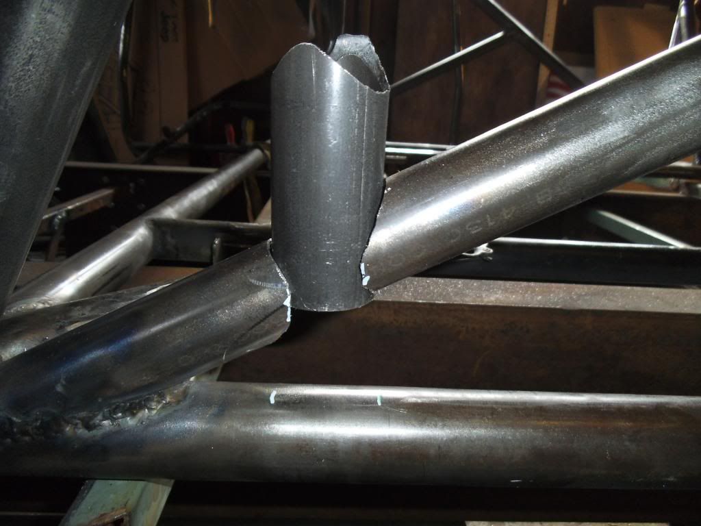
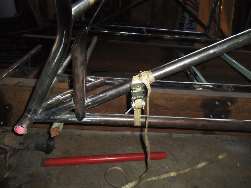
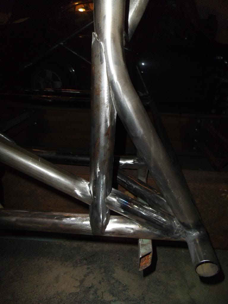
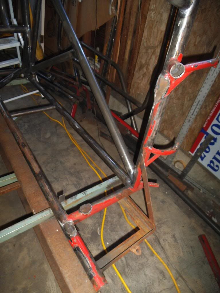
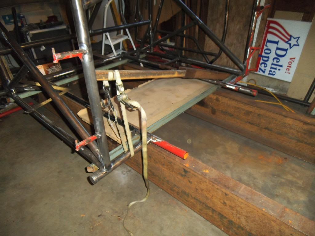
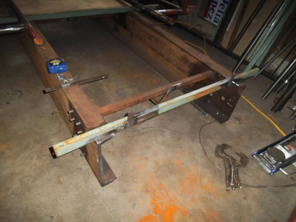
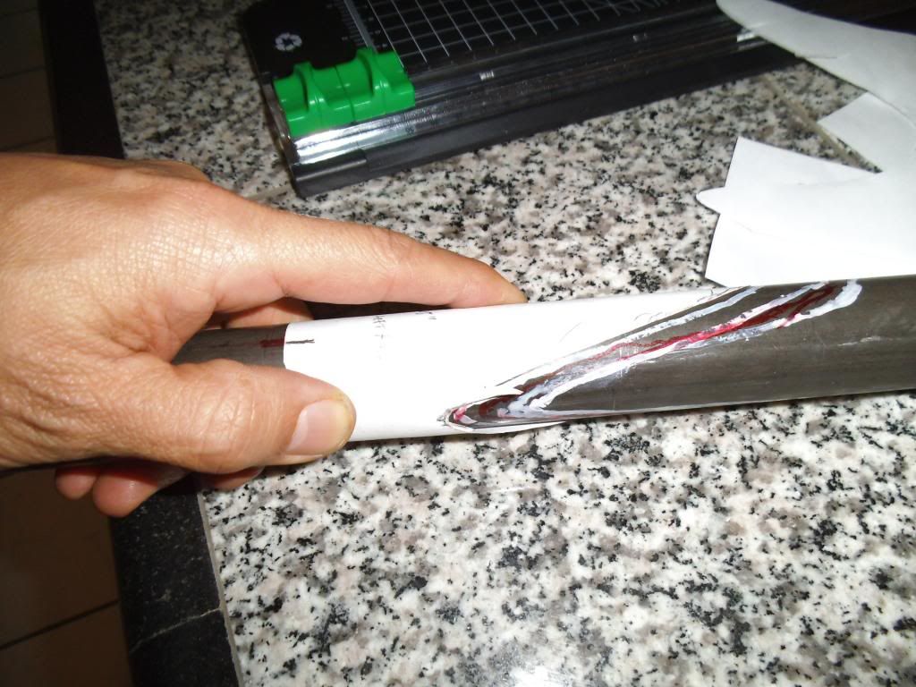
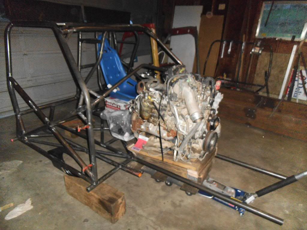
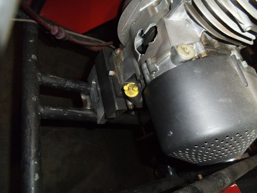
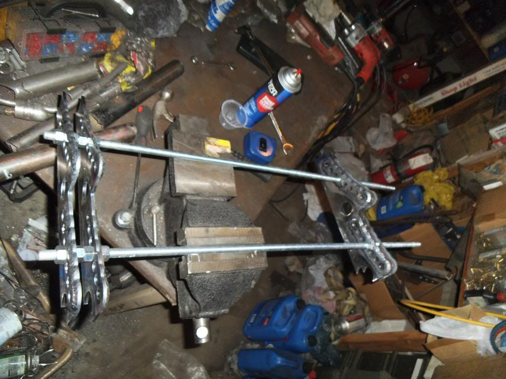
As you can see in this photo, sometimes you have to get a little redneck in supporting the workpiece while working alone.

10-new-being-notched-wide.jpg


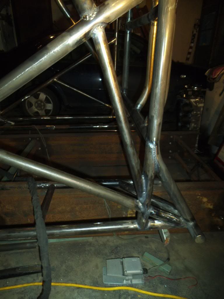
The redneck steps also include holding the main hoop with a ratchet strap while I tack welded it into place.
10-new-hanging-fitup.jpg


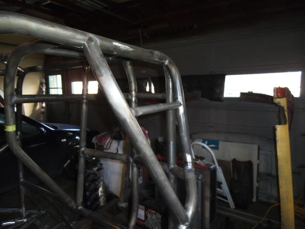
Next up was notching and welding in the new roof-pillar bar on the passenger side.
12B-being-notched.jpg


12B-welded.jpg


The door bars were next, which run from the main hoop at shoulder level down to the pillar bars down at the floor. These were relatively simple to notch, especially once I figured out some of the idiosyncracies of my new notching tool.

This photo was taken while mocking up with the old main hoop, so it shows another angle of the old main hoop.

New-16A.jpg


You can see here where I added a bend to give me a little more space with the driver's side door bar. I figure space between the cage and the door is wasted space, I'd rather have that space to be more comfortable, and to allow me to leave more space for the engine and trans towards the center of the truck.

Here is the passenger door bar installed:

17A-tacked.jpg


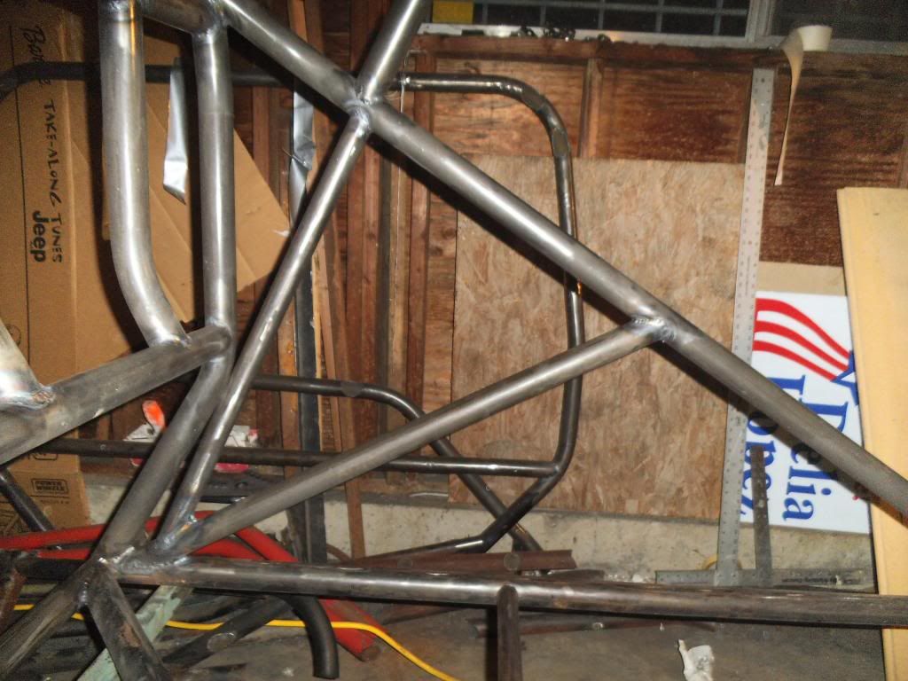
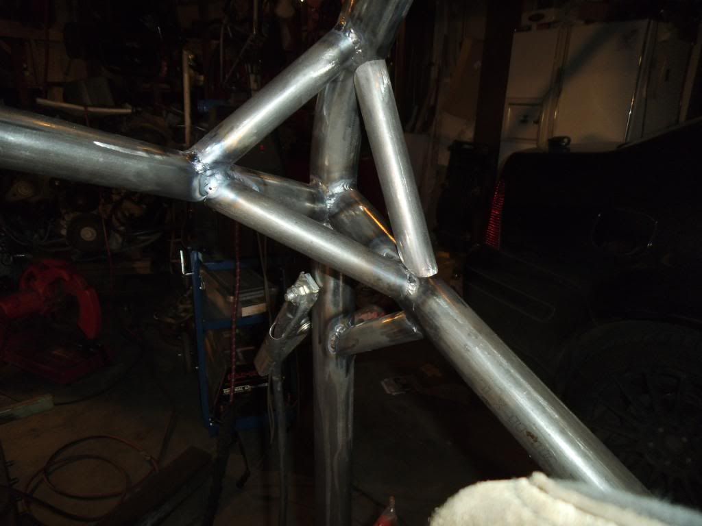
The X-bars in the door opening (lower rear to upper front) are divided up at the intersection with the door bars. This was a little tricky to notch, as the angles were beyond the capabilities of the notching tool. I did them by hand with grinding tools, a time consuming and frustrating task!

15-New-Tacked.jpg


17B-Duct-tape.jpg


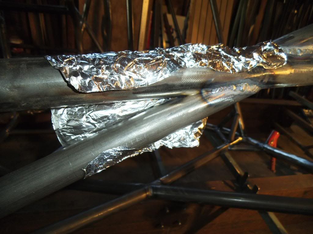
Duct tape is your friend when gravity doesn't help hold bars in place for welding!

I notched the top portions of these bars, but did not tack weld them yet since I would be climbing in and out of the cab area for all of the funny car cage construction.


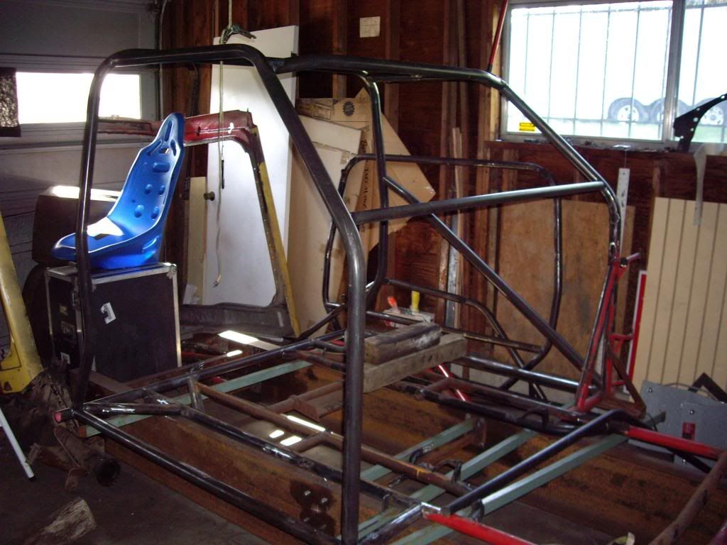
When I laid out my tubes for the funny car cage, I made the mistake of not mocking up the driver's seat properly, and had to revise the tubes accordingly. The main hoop angles in quite a bit towards the top, to follow the contour of the cab, and the tube that runs behind and to the left of my helmet ends up intersecting in the bend of the main hoop instead of at the top/horizontal portion. This ended up being a major pain to notch the tube, as it had a weird angle and was also tying in to where the pillar bar intersected. After MANY hours and a few cuss words, I finally got it notched and tack welded into place.

44-45-fit-rear.jpg


Since this bar effectively blocked off access to a couple of other joints, I had to finish weld those joints first. Most chassis builders will tack the whole chassis together then work their way around slowly doing the finish welding (to avoid having the weld draw pulling the chassis out of square). Working in small sections you can avoid heating up the joint to the point of causing this, but it is a lot more time consuming!

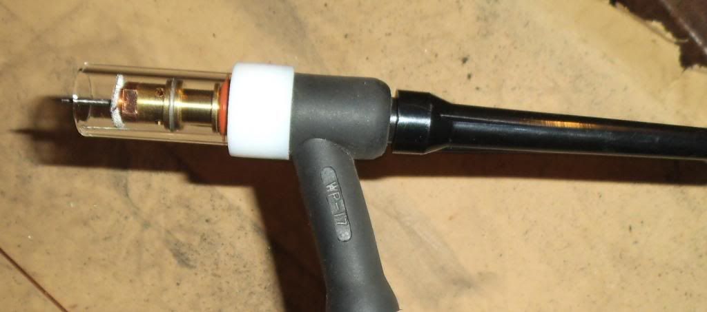
Working in these tight spaces required using the short end cap on the TIG torch, which in turn required breaking the electrodes off fairly short. I made it a point to be even more careful of not contaminating my electrode, because the "shorty" electrodes are a pain to sharpen!

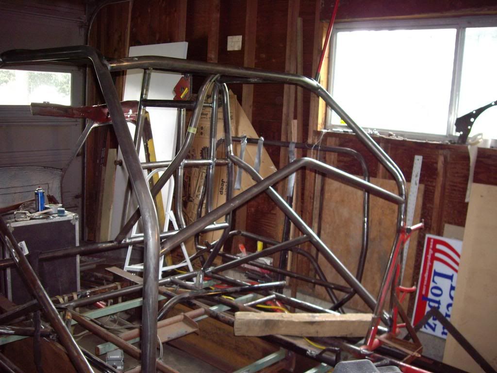
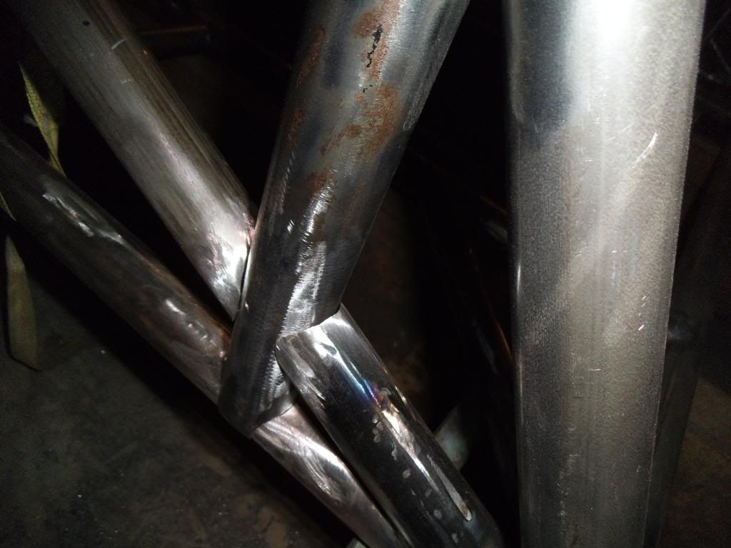
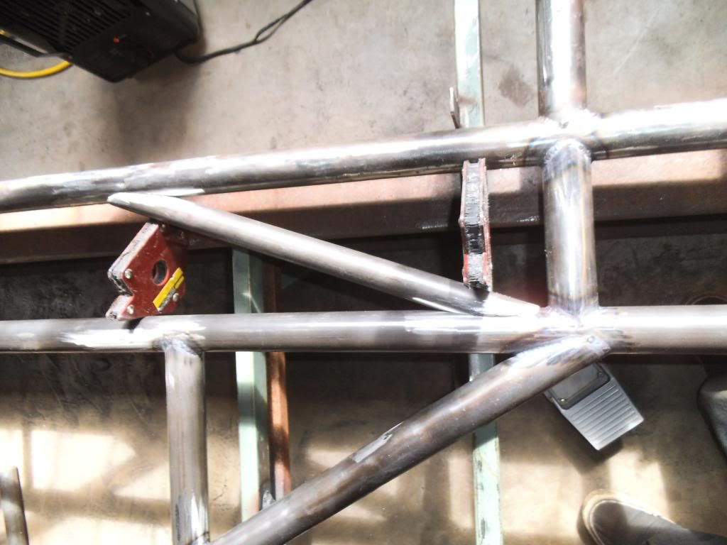
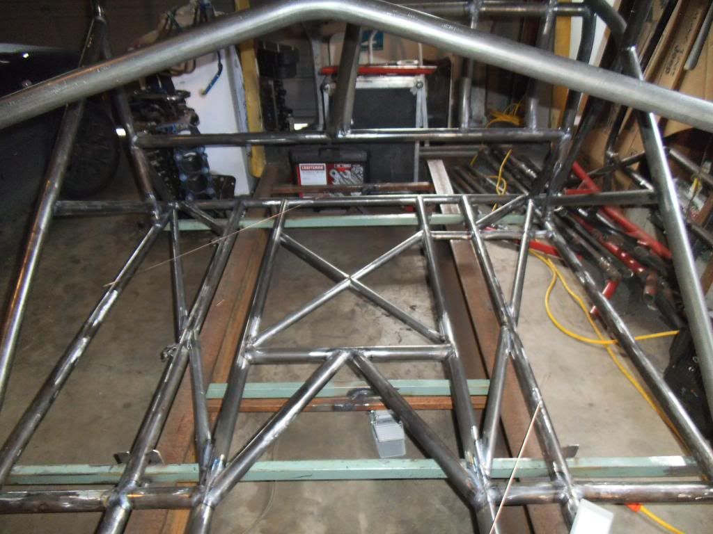
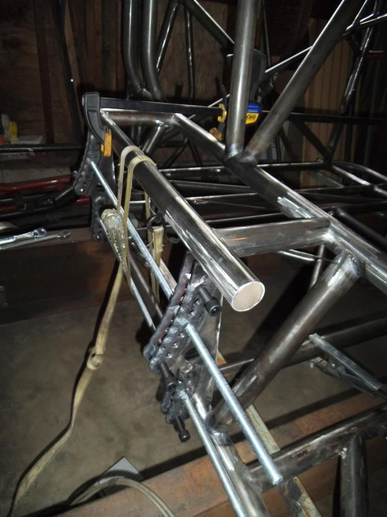
As I get more tubing in place, it becomes important to figure out the order that the next tubes will go in. For example, if you have two parallel tubes which will have another tube tying them together in the perpendicular direction, with the perpendicular tube properly notched you can't just insert it into place! If it is a snug fit you can't slide it in and rotate it perpendicular. I have tried to "think ahead" and not paint myself into a proverbial corner, but managed to do it on one pair of tubes. If you look at the parallel tubes in the photo above, I needed to get a cross-tube between them!

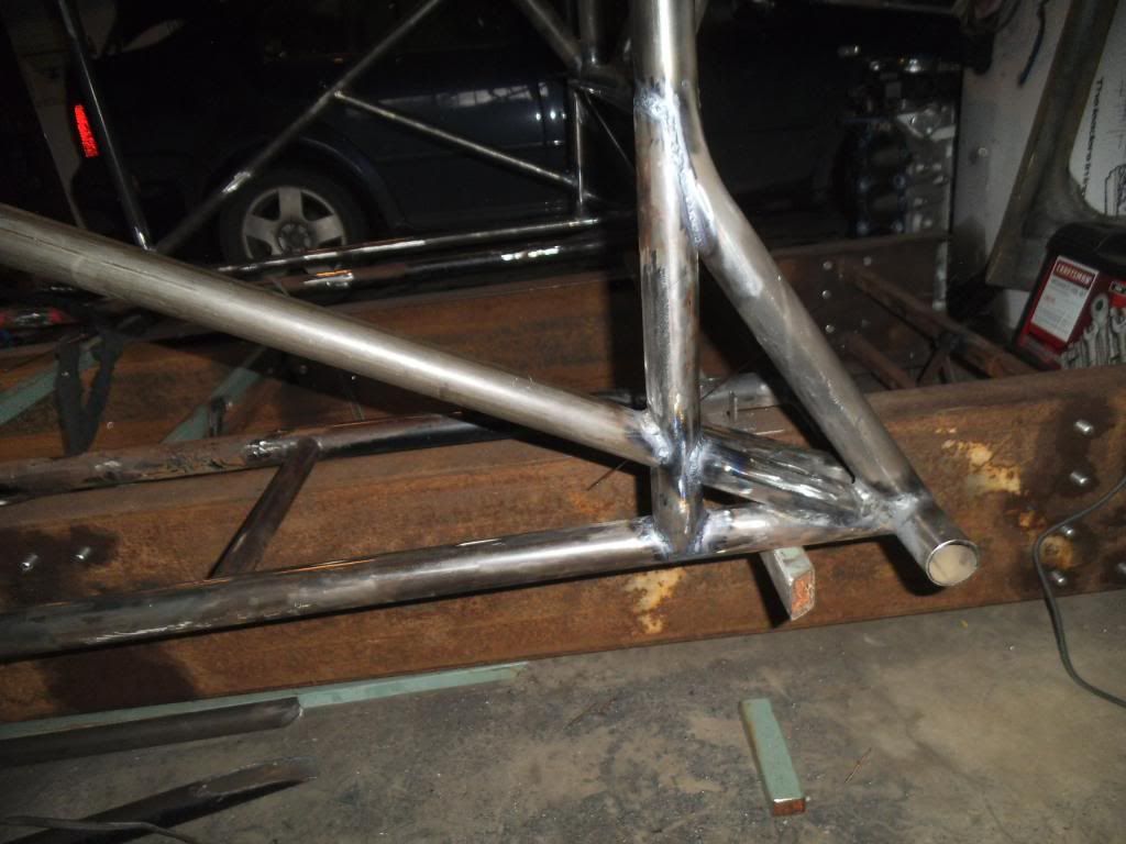
This was also a VERY important tube, as it's the one my harness will wrap around securing me into the car. The seat-back brace will also tie into this tube. I decided to make this tube larger and thicker than the minimum requirements because of this. I did NOT want to have any gaps in the mating joints, so I needed to spread the vertical tubes out and insert a properly fitted cross tube.

46-48-fit-ratchet-strap.jpg


48-fit-ratchet-strap.jpg


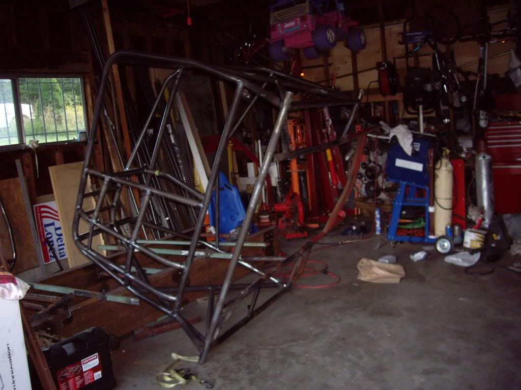
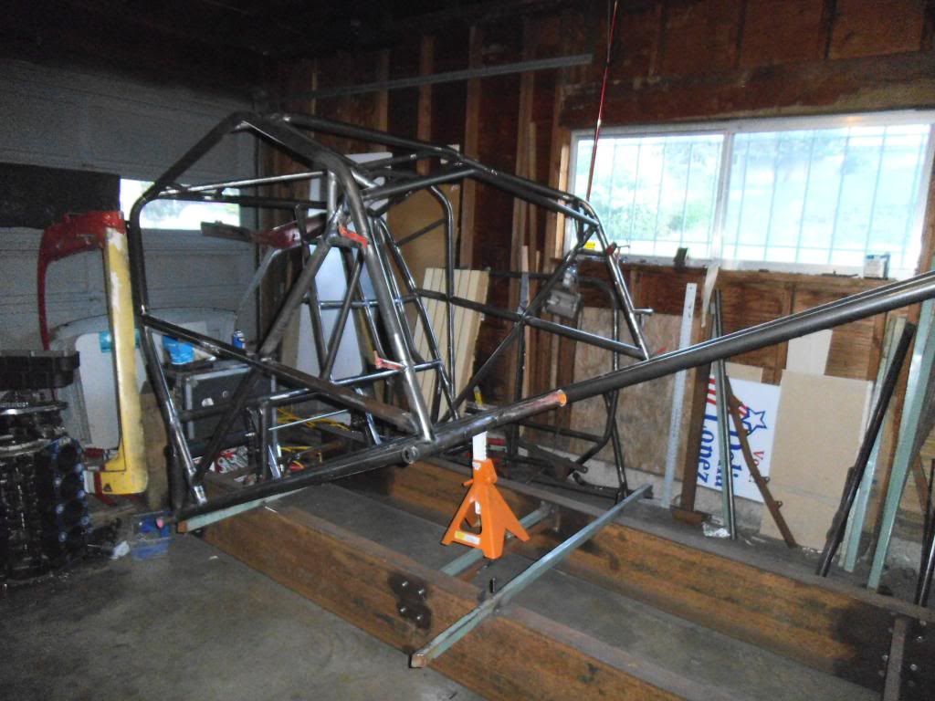
Building a chassis is inherently a redneck exercise, given the use of ratchet straps, duct tape and welders, and stuff is usually sitting with the wheels off and blocked in the air!

I'm getting closer to having the necessary tubes for the SFI certification of the chassis. I really want to get it certified before I reinstall the body and start doing the tinwork, both for the ease of inspecting it and in case I overlooked a tube!

Next up I will be adding the remaining tubes for the FC cage area, then the new bent dash bar, then a roof x-brace, then the floor with its crossmembes and x-braces. After that about 10 small gussets go in. Even though they are just short pieces of tubing, they take every bit as long to notch and install as a longer piece! With those parts in I can get the chassis certified.

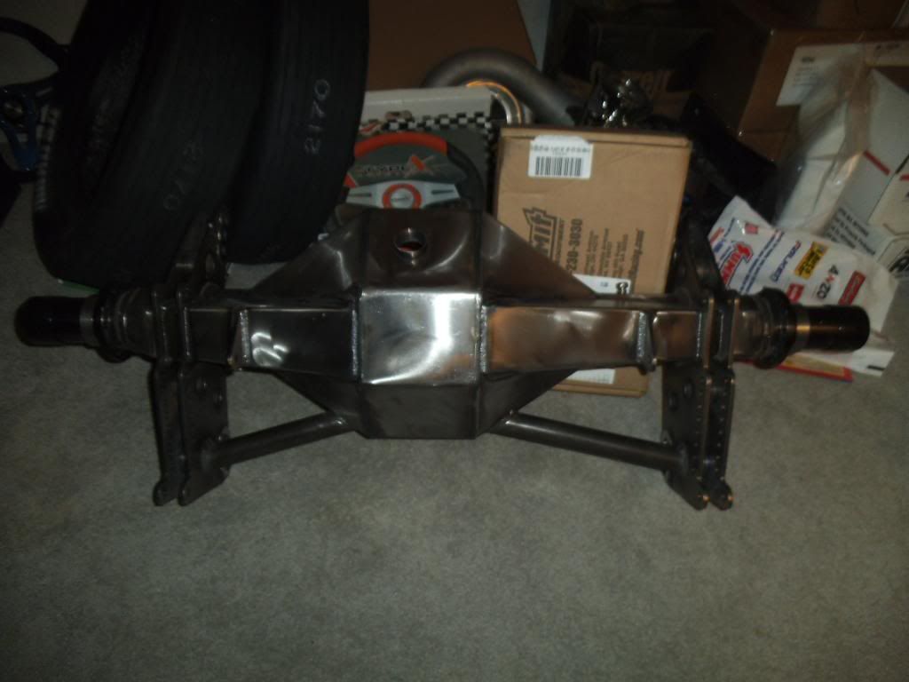
I've also obtained most of the remaining components for the build, except for the engine rotating assembly. I'll take some photos of those parts and post them in an upcoming installment.
 
I've been working on it again, and working on a new post for this thread with updated photos, should have it posted within the next few days!
 
Episode 12:
I know, it's been forever since I posted an update here. The theme of this post is two steps forward, about 4 steps back, then finally getting back to where I was!

I finished up the Funny Car cage area that I was working on at the last entry, and also added the "kidney bar" that runs next to the driver.
40D-old-welded_zps5e30a4cf.jpg


Searching the internet for a different piece of information I came across a post from someone on the SFI update committee, saying that they are planning to change the spec to require the dash bar to intersect the pillar bars at virtually the same location as the door X-bars. There is no limit on the distance in the specification, but in the "top secret decoder ring" handbook they give to chassis inspectors, they mention something like a maximum gap of 3x the diameter of the largest tube in the junction. This would have allowed me a 4.875" gap which I was planning to take advantage of, moving my dash bar as high as possible to clear the high pressure turbo.

I had already removed the old dash bar and welded in a replacement in this location:
12B-welded_zps0853a8fc.jpg


My chassis would get the certification 1st time out, but once the rule changes I would need to replace that tube for the next recertification (3 years later). I'd rather do it now and be good, so I switched to a bent dash bar to get the turbo clearance I needed:
11-New-bent_zpsda99ca08.jpg


When it was time for the ISSPRO Pacific Coast Diesel Nationals I went ahead and mounted the cab & doors, so we could have something in our booth to attract attention. Fortunately this portion of the chassis is light enough to just slide off the jog:
Tipping-off-jig_zpsa4443253.jpg


I started out carrying the thing "Fred Flintsone Style", but ended up tying it to a hand-truck with a ratchet strap.
On-Handtruck_zps404fd331.jpg


I had previously gotten written approval for how I wanted to build some portions of the cage, trying to meet the letter of the SFI spec even where it was difficult due to the shape of a truck versus the car chassis that the rules reflect. I didn't like the way I had to build it to meet the rules, but at least it met the letter of the rules (and I was adding some supplemental gussets to make me comfortable with the design). Unfortunately once they saw it in person and photos, they didn't like the way it laid out either. That whole issue brought my progress to a screeching halt! We went back and forth discussing alternatives, and it went all the way up to the head of NHRA's technical department, before we finally agreed on a design and has their written approval.

The key areas were the base of the main hoop. I planned to add some vertical gussets, but leave the required diagonal and "kidney bar" tubes continuous and make my gussets interrupted by those tubes (since the gussets aren't required by the spec). They came back and wanted me to do full diameter gussets that were not interrupted (which is the best thing for strength but technically violated the spec).

I was torn about whether to completely tear that whole area out and start over, or to try to "graft" the new tubes into place as well as I could. Since one tube (the kidney bar) was moving locations and getting shorter, I figured I would just remove it and replace it. Since the diagonals were already fully welded and in a position that would be difficult to grind and smooth when removing the old pieces, I decided to try to leave them and cut holes for the new gussets to pass through them.

Here is the passenger side after using the plasma cutter to rough in the cuts. I learned after these cuts that my electrode was worn on the cutter, which kept me from making very clean cuts.
17B-plasma-cut_zps2041c50e.jpg


I used a short piece of tubing to check if I had notched enough for clearance, as the tube above kept me from easily dropping the actual length tube into place.
17B-fitted_zps8d6b63f8.jpg


I had to use a ratchet strap to flex the diagonal out of the way to allow dropping the new bar into place.
17B-ratchet-strap_zpsaa678aef.jpg


The driver's side was even more difficult since the door bar is bent outward (giving me more elbow room), which puts all these parts at slight angles.
16B-gusset-fitted_zpsf6580161.jpg


DSCF1110_zpsd0eedc2b.jpg


Here's a little detail you need to do when welding on a short section of tubing - a hole to allow the air in the tube to expand into one of the longer tubes. Without this, as you finish the last section of weld bead it may "blowout" from the air in the tube heating up. Been there, done that!
16B-gas-hole_zpse13834a6.jpg


DSCF1114_zps5832ef8e.jpg


The new path for the kidney bar put it at a sharp angle with the tube it connected to, which precluded using my notcher to cut the required "fishmouth" shape, but a large carbide burr in an electric die grinder worked wonders for quickly shaping it.

With the replacement of the kidney bar, I was FINALLY back to the stage I was at on the project back in August!
DSCF1119_zps9cb474ac.jpg


While waiting for the NHRA decision I had plenty to keep me busy, between racing my Vega and working on my daughter's Junior Dragster.

Both of those endeavors provided success and mechanical failures! My daughter won her first event in her Jr:


I won a few events in the Vega, including a big bracket race that was complete with a big trophy and giant check. This race had some of the best bracket racers in the NW, I felt really fortunate to come out on top!
207455_400847239977290_78184997_n_zpsdb863fd3.jpg


Unfortunately some bad things came along with the good. At a bracket race up in Bremerton I had a piston break towards the top end, and blasted out the sides of the block and oil pan. Despite having an engine diaper, the thing still locked up solid and sprayed a bunch of water and oil onto the tires. Fortunately Bremerton is built on a backup runway, and the guardrails are waaaaay off to the side, so I had plenty of room to do a 145+ mph slalom trying to bring it to a stop.

Back at the trailer I could see this was going to be expensive, as a huge crack was apparent in the cylinder head:
IMGP0531.jpg


It appears that the #1 piston broke, and the rod and pin then flailed around and busted up everything in their path.
IMGP0543.jpg


I was concerned since the very next race was the Race of Champions at the ET finals (which I was fortunate enough to qualify for the 2nd year in a row). I had a cracked cylinder wall at last year's RoC, and the car was smoking like crazy but I was winning rounds (got down to 5 cars left). I ended up buying a complete spare engine from a friend of a friend (ironically a few miles from the track I broke at, but of course a few days later so I had to make the trip twice). I didn't realize it at the time, but it appears I damaged the front pump on the transmission when the engine let loose, so the first pass at the RoC I ended up pumping all 10 quarts of ATF under the tires at the top end of the race track, and got to do another 145+ mph slalom (and miraculously kept it shiny side up and off the walls). A bunch of friends pitched in and we rebuilt my trans in the pits, and I was able to go a bunch of rounds on the Sunday race at the ET finals. I also went a bunch of rounds in my truck in a cash bash during the RoC (made it to the semis).

With my daughter's Jr, we had kept the engine slowed down with a restrictor plate on the intake. The engine was capable of mid-10's in the 1/8-mile, but as an 8 and 9 year old she was restricted to 12.90 and slower. I had picked up a couple of 8.90 engines, but learned that we needed a much better clutch to handle the additional power (and the good ones are built to order and take several weeks during the racing season). We went to the 1st race after her 10th birthday, planning to open up the old engine and let her run some 10's. Unfortunately the engine had other plans, as it broke a connecting rod right after firing it up to warm it up!
2012-09-23113552_zps00c7e00c.jpg


The worst part was seeing the disappointment on her face when she realized we weren't going to be racing that day.

Now that I have a much better idea of how long each task takes in the chassis build, I was able to create a project plan to help organize the remaining tasks and estimate a completion date. It now looks like I should get this whole thing done sometime in mid-June, just in time for the ISSPRO Pacific Coast Diesel Nationals!
 
Last edited:
Episode 13:

One thing I forgot to add to the last update: I hadn't driven the MBRP Dirtymax in a while as I was working on this truck, but the opportunity came up to drive it at the last 2 events of 2012. We ended up winning the World Championship in NHRDA Pro Stock!
2012-Ennis-DSC01213_zps993e530d.jpg


The coolest thing is that over 40 million viewers tuned in to watch the event on Fox Sports Net! While that's great for the sport, I have to remember that it's probably a small fraction of the people who watch Honey Boo Boo (and no, I never have)...

A couple more sponsorship-related items:
Would you please "Like" our ISSPRO facebook page? It will help show the bosses that sponsoring this truck is a good thing! http://www.facebook.com/IssproInc

We are happy to announce that Mahle has signed on as an Associate Sponsor, and we will be running Mahle pistons in the truck. Don't tell them, but even without sponsorship help I would have gotten their pistons anyway ;)

After all that excitement it was back to the garage! As I started finish-welding some of the junctions of several tubes, I found that I had to extend the TIG torch's electrode so far out that I didn't get good shielding gas coverage. I had planned to pick up a "gas lens" for the torch, which is something that focuses the flow into a nice even column of gas. I ended up getting a specific version of the gas lens called a CK Gas Saver, which is designed to work well at reduced argon flow rates (saving some money in the process). It was also cool that its cup for the shielding gas is a clear pyrex-type glass, giving better visibility of the arc and puddle.

DSCF1123_zps9a384bca.jpg


I tried it out and it was awesome! Unfortunately it was also breakable, and I set the torch down on the jig to grab more filler rod, and it slid off and broke! I ordered some spare parts and got it back together. This thing would have already paid for itself in reduced gas costs, had I started using it at the start of the project. Heck, it is worth it in reduced blood pressure from trying to make some of those long-reach welds work!!!

Next up I installed the "X" braces across the roof of the cage. The corner mounting points resulted in some weird complex angles, so the tube end fitting was difficult and cumbersome (but then again what HASN'T been on this build???).

DSCF1120_zps8cf03ff0.jpg


One item on tube fitting that is worth mentioning: when you use a notcher to cut the contour in the mating tube, the farthest forward edges end up downright sharp.

DSCF1140_zpsdd2346a5.jpg


As I discovered early on, if you don't "blunt" those edges with a grinder, you end up with a very thin section when you weld, and if the weld puddle is at the edge of the tubing you will end up with a hole as the thin section melts away. By blunting the edges you move the weld location to where the tubing is full thickness.

DSCF1147_zps567b7e79.jpg


I decided to go ahead and flip the chassis over and get at all the weld spots I had skipped to this point. Once I add the front of the chassis it will be a lot harder to flip and maneuver in my little garage!

DSCF1125_zpsa52791ad.jpg


I removed a diagonal from the firewall area, as that section will be extended to give me more room for the pedals. It was nice to have my plasma cutter working well again, having replaced a worn out electrode!

DSCF1128_zpse02502d3.jpg


With that diagonal out of the way, I found that the section of the original floor had a twist to it, and needed a little "persuasion" to get it flat:

DSCF1130_zpsa0439189.jpg


I added a new crossmember and alignment tabs for holding the front frame rails into the jig.
DSCF1133_zps9af7f582.jpg

DSCF1136_zpsbf55bfe9.jpg


One of the things I am trying to do is come up with quicker ways of doing some of the repeated tasks in this build. One of those tasks is cutting small strips or plates of metal, either for the jig or for brackets on the chassis. When I built my gasser chassis many years ago I borrowed a Whitney shear and punch from my family business, which allows me to make short work of many of those tasks. I went ahead and found used versions of the same tools on ebay to use for this build.

DSCF1131_zpsba6ec3a3.jpg


As I started laying out the details of the floor area, I decided it was worth it to lay it out in CAD so I had a better starting point for the measurements and angles of the tubes I was going to be cutting and notching. I was hoping to do this in a solid CAD model, but I hadn't touched a solid/3D CAD program in MANY years! I had been using a freeware 2D program for the last several years to do simple stuff like laying out the rear frame of my small block Vega, and designing the parachute mount for my big block Vega. I found a decent solid modeling program with a free demo, but was still learning it and decided to just get it done in the 2D program I was familiar with:

floor03-dims_zpsd82122fd.jpg


I discovered that the freeware version didn't allow angular dimensioning, but the "Pro" version was only $37.50, and I've gotten waaay more utility out of their package than that over the years!

As with the prior spreadsheet I had used to organize the tubes I needed, this would help me optimize the cuts so I could get the most usable tubing out of the lengths I had. Plus it was something to do while thawing my toes on the really cold mornings of working on this chassis! The drawing would also help me figure out which tubes had to go in a specific order, to avoid "painting myself into a corner" like I did in the funny car cage area. With the larger diameter tubes that make up the main floor bars, the ratchet strap trick might not work!

Armed with the CAD drawing I was able to locate and sand down all of the spots on the main tubes where there would be welds (much easier while I could tip up the chassis), then started cutting and notching the tubes for the main floor pieces.

DSCF1138_zps8e456ada.jpg


Yes, it looks like it's snowing or smoky in my garage from all the crap in the air from the metal prep work. After seeing that photo I decided to go back to using a respirator when doing that type of work!

Another thing you learn quickly about TIG welding is that the tubing needs to be REALLY clean both inside and out at every joint. When I started this work I was only cleaning as much as I used to do with MIG welding on mild steel, and the result was a weld puddle that snapped, crackled and popped like Rice Crispies on steroids. Now I use lots of carb cleaner to degrease, then a sanding disc on an angle grinder, plus a sanding roll on a die grinder to clean up the inside, then a final cleaning with carb cleaner. I make sure to NEVER use brake-cleaner, as some blends include chemicals that will turn into poisonous gas when exposed to heat.

I have now received written "blessing" from the NHRA on the photos of the previously disputed areas, as well as my CAD drawings of the remaining fabrication before the chassis certification (which should happen in just over a week when the certification tech comes to our local track). It's tough to get a lot of work done while still spending "quality time" with my daughter (and she's going through a "girlie girl" phase where she doesn't want to get dirty in the garage), so I've been mostly working after 9:30 pm and between 4:00 am and 6:30 am. I do my best to always keep the doors closed when doing something noisy, but my neighbors probably still hate me!
 
Good write up Michael! I wondered how the pyrex would work. I've threatened to get one, but now that I know I would crush it in minutes, I'll pass. :) You can also use Acetone to prep. Every single TIG joint I do is wiped inside and out. Stainless I try to backpurge as much as possible. Keep it up! I can't wait for this thing to be rolling!
 
Good write up Michael! I wondered how the pyrex would work. I've threatened to get one, but now that I know I would crush it in minutes, I'll pass. :) You can also use Acetone to prep. Every single TIG joint I do is wiped inside and out. Stainless I try to backpurge as much as possible. Keep it up! I can't wait for this thing to be rolling!

Does the acetone work any better than carb cleaner? Both had been suggested to me, but carb cleaner was handy since I always have it in my garage anyway! The CK gas saver is available with conventional ceramic-type cups as well (I picked some up in case I go through a stage of repeatedly breaking the pyrex again). The cups are also available in the standard sizes like normal torch cups, which presumably will allow fitting in a few tighter areas without as much electrode protrusion. So far I haven't broken another pyrex, I just have it drilled in my head to ALWAYS either lay it on the floor or hang it from a hook. If I'm working up high I use a baling wire hook to securely hang it when grabbing more filler rod.
 
I don't know the answer if acetone is better. I always have it around because it cleans fiberglass resin.

I use a gas lens cup for most everything now. I had to switch back once because the lens was too fat to get in the corner.
 
Episode 14:

At my last update I had finished the roof structure of the cage, next up was the floor.

I decided to build a generous "footbox" area, allowing me to have the pedals forward of the main firewall area. I wanted to be able to use brake pedals with a very long stroke, to allow me a lot of leverage to create very high brake pressure. This is to hold the truck while building boost before bumping into the staging beams and engaging the transmission brake. I also needed extra width on this footbox since I planned to use two separate braking systems on the truck, both for functionality and redundancy in case of a failure. One system will be pretty much a typical race car braking system, with one master cylinder actuating a pair of calipers on the front wheels and one pair on the rear wheels. My secondary system will consist of a second master cylinder, with a separate pedal positioned right next to the other one, and it will actuate a second set of rear wheel calipers, with these ones equipped with brake pads with very aggressive cold temperature friction. I will be able to center my foot over both pedals while building boost, then just use the "regular" pedal when slowing down after a pass, and if something fails in the main braking system I can use the secondary system to slow down. I was hoping to run a system like this, but until a few months ago the NHRA had banned secondary braking systems (yeah, I know, it seems ridiculous to ban a backup safety item).

Since I would have my feet beyond the "protection" of the main cage, I needed an additional tube that far forward:

DSCF1155_zps9172b18e.jpg


As I started on the various braces across the floor, I ended up with a sharper angle than could be cut with my notcher. To make things even more difficult, I decided to offset these tubes so the tops were flush with the larger main floor tubes.

DSCF1160_zpsd14c92e0.jpg


I would be duplicating the same angle 8 different times, so I knew there was a better way to do this than trial and error. I ended up hand-shaping the first one, then making a paper template for it:

DSCF1159_zps98a37a76.jpg


DSCF1157_zps210ffdda.jpg


I used the template to draw the contour on the tube, then used my plasma cutter to rough cut the shape and a die grinder with a carbide burr to do the finishing. For the spots with the mirror image of that contour I just turned the paper pattern inside out.

Another mini-challenge was a spot where I needed to notch both ends of a very short piece of tubing, and it was too short to be retained by the notcher clamp. I just stuck a smaller tube inside it, and a short section of the same diameter tube as a spacer, and clamped the whole mess in the notcher:

DSCF1163_zps08c121ea.jpg


DSCF1164_zps7887aa69.jpg


As I placed the floor diagonals I was bound and determined to weld things gradually and slowly to avoid warping the chassis again (starting with all of the pieces tacked in, then moving around and welding small sections in different areas, stopping frequently to let things cool).

DSCF1168_zpsc47e65af.jpg


I decided to spend some of that cool-down time unpacking the Fab9 rearend housing from Chris Alston's Chassisworks. I had previously noted that they packed the entire box full of spray foam, meaning I literally had to dig out chunks of spray foam to get the rearend out:

DSCF1196_zps10db45e9.jpg


DSCF1197_zpsd1843abc.jpg


DSCF1202_zps0566e430.jpg


It was a fun but messy time for me and my daughter. We made a huge mess and filled up 3 garbage bags with the spray foam chunks!!!

One "gray" area in the spec was whether or not I needed an additional helmet bar on the side of the funny car cage (as my helmet would not fit through the opening, but it came close). I decided to err on the side of safety and add that bar:

DSCF1207_zps9d2229c8.jpg


It was also time to start adding a bunch of little gusssets as required by the spec:

DSCF1223_zps59c179ec.jpg


While welding these areas and "skip welding" around I found myself having to put my torch hand onto areas where I had recently welded. I have seen advertisements for a device called a "TIG Finger" to protect that finger while dragging it along. I recognized the material as being the same as spark plug boot heat shields. My diesel friends might be asking what a spark plug is, but it is a contraption necesssary for gasoline engines to run ;) I had a set of those heat shields tucked into the trailer, so I grabbed one and kept welding:

DSCF1227_zps91f7a734.jpg


After finish welding all of those tubes I decided to mock up the engine & trans in the chassis, to figure out their positions and how much clearance I would need:

DSCF1267_zps2b16663d.jpg


DSCF1294_zps4b678aa0.jpg


I ended up deciding to move it back 2" more than I had in these photos, to match up with my prior calculations for front end weight percentage. It will be interesting to see the final product and if the numbers match up with the theoretical values in my design!
 
Episode 15:

As I was welding the angled floor bars together I found it hard to get decent shielding gas coverage when I had to extend the electrode well past the torch cup. I came across an online tip that worked well here - adding aluminum foil as a gas shield to create a little "pocket" of gas. It also helped to remember that Argon is more dense than air and will "fall" from the torch.

DSCF1255_zpsa1ee4f6e.jpg


My progress was briefly interrupted by some necessary work on my gasser race car. I had a starter hang up near the end of last season, which chewed up a brand new SFI flexplate:

DSCF1302_zpsfaca3f41.jpg


This necessitated a quick engine removal and replacement. The mid-plate flexplate shield prevents me from removing the flexplate without removing the engine. I had a busy time as I headed home from work with the engine still hanging from the engine hoist, but managed to get to the track in time to race and even win a few rounds!

DSCF1303_zpsb4c797d6.jpg


I also had to completely revamp the drivetrain of my daughter's Jr Dragster. She turned 10 just as the tracks were shutting down for the winter. As an 8 & 9 year old she was restricted to 12.90 1/8-mile ET, but they make a huge jump to 8.90 ETs when they turn 10. The original engine should have gone about a 10.50 with the restrictor plate removed. We found an end of year race running Jrs and headed out of town for it. I had just fired up the Jr to warm it up, and the throttle seemed a little bit lazy to respond. I went to rev it up a few hundred RPM and had the connecting rod blast through the block!

DSCF1320_zps54880a1e.jpg


I had previously bought an 8.90 engine for the car, and had a decent clutch on order. As I discovered, our ancient chassis meant that none of the "off the shelf" parts would be a simple bolt-up. I had to fabricate a lot of the mounting brackets, to achieve the proper belt tension and engine angle.

DSCF1335_zps9a05d87d.jpg


After all that I switched back to working on the race truck. I actually liked the distraction to give me a chance to mull over the 4-link mounting brackets, as this is one of the most important sections of the chassis. I decided to use lengths of threaded rod to space the brackets out perfectly. I even sorted through an entire box of nuts to find the ones with the closest measurements to stack together and automatically hit my desired gap in the brackets.

DSCF1305_zps54dbd52d.jpg


I clamped the whole mess together and spent a BUNCH of time making sure everything was aligned perfectly, then tack welded it and proceeded to weld it in place a little bit at a time!

DSCF1339_zpsaf6a8d56.jpg


I decided to let gravity augment my welding skills while adding reinforcing plates to the 4-link brackets:

DSCF1351_zpsad3ff32a.jpg


DSCF1353_zps12f339dd.jpg


It would have been a better appearing weld if I could have done it in a single pass, but there would have been way too much weld draw, leaving the brackets crooked in the chassis.

One of the SFI rules requires that you have an official "builder" identification plate on the chassis. I was able to bring it to work and have it done on a CNC engraver:

DSCF1356_zpse3bc2d95.jpg


At that point in time there was a National Open event where the whole NHRA tech crew would be in attendance, so I headed up there to race my Vega and to get this chassis (hopefully) certified. The cert tech spent a while looking over the prior correspondence between me and the division tech director, then looked over my chassis. We had the whole big issue of trying to meet the letter of the specification but accommodate a stronger design for my main hoop tying into my main crossmember. The tech looked it over and asked why I didn't just put a bend in each end of the main crossmember and move the junction point to where I needed it. Crap!!! Why didn't I think of that!!! That change would have saved me a bunch of time and headaches, but it is water under the bridge at this point! After MANY hours and hassles I finally got my chassis certification!

2013-05-12101044_zpsb9f5f7f2.jpg


After realizing how often I was refilling the 83 CF argon bottles while welding all this stuff, I traded up to a 150 CF bottle (which barely costs more than the 83's to fill):

DSCF1354_zps615e2717.jpg


I kept my second bottle as the smaller 83 CF one, I only use it to finish up if I run dry on the big bottle, and I'll keep it in the trailer when we head to out of town races.

As I started working on the remaining design aspects of the chassis (strut mounts, rear frame including shock, anti-roll-bar and parachute mounts), the need for a 3D CAD model seemed more critical then ever. After being disappointed with lower cost commercial packages I came across the latest version of Freecad, an open source software package (and FREE!). I tried the then-current version when I started this project, but it had way too many unfinished features. This one really impressed me. It still has a few glitches but works really well otherwise. Here is my model (with some items represented in rough form, like the strut top mounts are just as cylinders, and the engine only shows the balancer and mid-mount plate). I also left out sections that are already done and don't really need any more design work (top of cage, floor diagonals).

Chassis11b_zpsb8fb2f72.jpg


I suppose things were seeming like they were going too well, so something had to happen!

We headed up to Canda for the BD Diesel event at Mission Raceway. It was a chance for my daughter to get in two separate races in her Jr, and it was also a big bracket race that I would run my Vega in (as well as my dually in Sportsman ET). I was excited for Caitlyn as we finally had all the issues ironed out in her car, it was running VERY consistently and she was cutting killer lights. One issue she has with unfamiliar tracks is seeing where the 1/8-mile finish line is. At our home track they only run 1/8 mile for the weekly bracket program, so that finish line is well marked with a big white stripe, and no more cones past the finish line. At other tracks you are lucky if there is any stripe at all, and there are cones at the 1000', 1254' and 1320' marks. To compound matters they expect the Jrs at this track to make a U-turn on the track in order to make the return road. I took her down to the return road area before we ran, and she said she had a good look at it. On her 1st time run we derailed the chain (the tensioner had vibrated loose on the long tow there). On the next pass she cut a good light and make a perfect pass, but stayed in the throttle way past the finish line, then tried to turn into the "switchback" return road entrance before deciding to try to go back onto the track (which is what I always told her to do if she misses the turnoff). She ended up hitting the wall at a 45° angle, smashed up the car pretty well and gave herself a mild concussion and severe leg bruise.

2013-06-01124500_zps594964cb.jpg


The left front wheel was mangled and torn from the chassis (hanging on by the now-bent steering linkage), the rear axle broke on the impact sending the left rear tire hundreds of feet away in the motocross track, and the cage got flattened from the impact. The front section of the chassis is also pretty bent.

A good friend of mine (Dan Soran) builds race cars and has done a complete Jr for his sons to race, as well as a bunch of updates on area Jrs. He had previously suggested that we borrow their car and run it, as it is a nice state-of-the-art chassis (and ours is quite outdated), and it would be a chance for exposure for him to sell it. I decided to take him up on that, and also spent a few hours bending up tubes for rebuilding our car, as well as some tubes for the brake assembly for the race truck. I was originally planning to take my dually, but since it is a 800+ mile round trip I decided to see if I could successfully tow with my TDI Jetta. It towed great once I took the slop out of the hitch receiver. Nothing like getting 38+ mpg while towing!
2013-06-08180126_zpscd4da329.jpg


As we get closer to the annual ISSPRO Pacific Coast Diesel Nationals (June 29th in Woodburn, OR), it is painfully obvious I won't have my truck running for it. I will have it on display though, hopefully rolling on its own rather than on a hand-truck like last year! Please come out and join us for this event. It will be quite an event, with the $6500 purse for Super-Street, plus the sled pulls, and a big "Top Comp" fast gasser race to fill in the time between the diesel passes. Of course the complimentary ISSPRO BBQ will be back as well. Hope to see you there!
 
Love the updates Michael! Been following most of it on facebook but it's nice to see it all in one place!
 
Back
Top