Beam repair on a 4 post lift. ? for the engineers/guys who know stuff about things!

Sandaholic

Bangin' through the gears
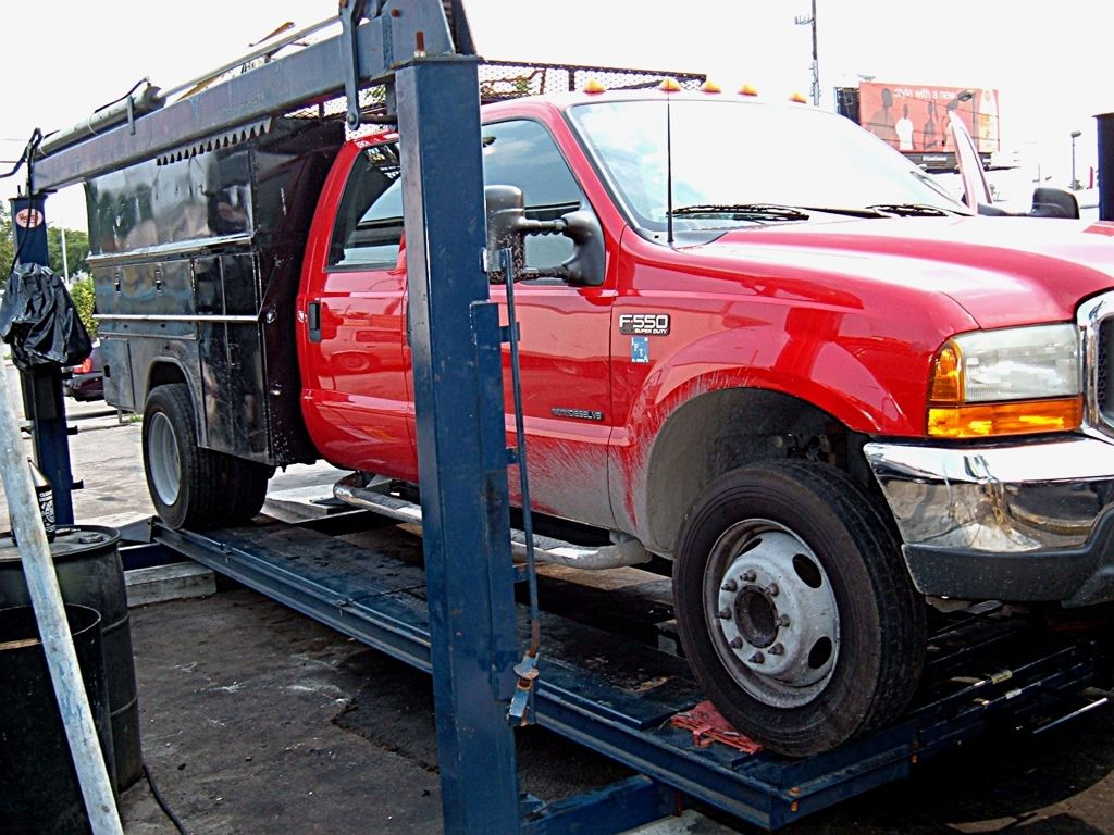
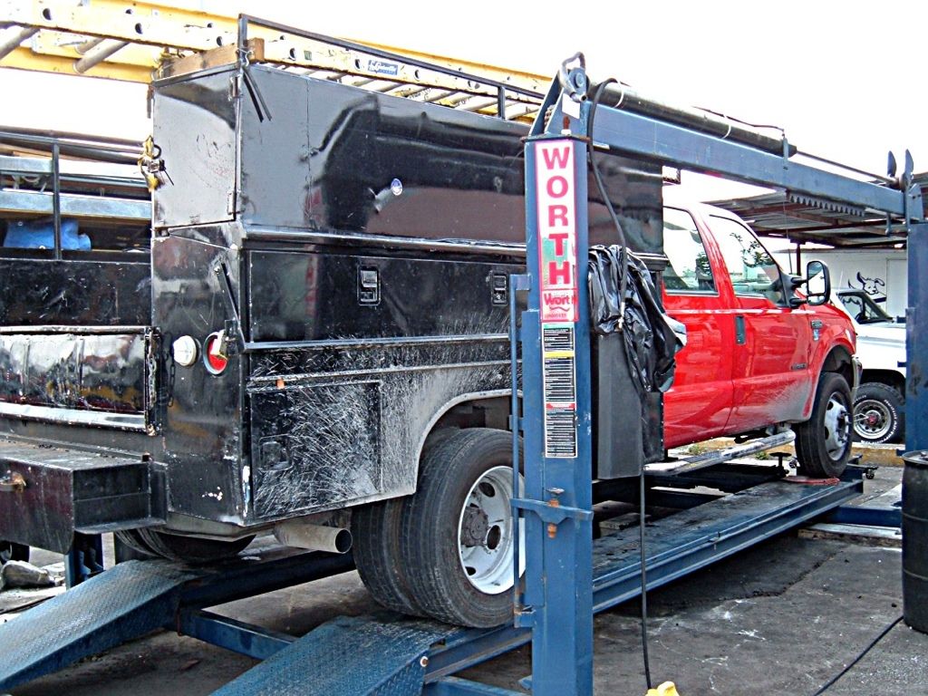
I'm going to be repairing/modifying a beam on a four post lift. This lift is used to do alignments and has been replaced once already to factory spec. It has since drooped again in the middle which screws with the alignment equipment. It is a 10' span of 5"x3"x.25"wall rectangular tube. The drive on platform/ramps are 5'6" apart and 1'10" wide each. I was asked if I could replace it with a .375 or .5" wall tube.

My question is how much more strength will either of these be over the .25" tube? IIRC the heaviest rigs they put on the rack are 15k. And the .25 tube lasted for years, but over time it has sagged to the point where it needs to be fixed again.

I have another idea to fix this thing which IMO will be way less involved. The other plan is to cut the beam up the center leaving the top intact. Bring it back to level or just a hair high. Weld it back together and then full length plate it on both sides with .25" or even .5". Or plate it all the way around if that will really increase the strength. Extra weight will not bother this thing at all. The ramps are already a little too steep for some cars so going to a deeper beam like a 5"x8" is kinda out of the question.

I have the go ahead to do it either way.
 
I would cut it up the middle and put it like you said and get some angle iron and put on there. I do not think the thicker wall will help that much. Maybe try a higher grade steel instead.
 
You don't really need to plate it all the way around, I would just plate it in the vertical plane. That appears to be where the forces are acting.
 
I would cut it up the middle and put it like you said and get some angle iron and put on there. I do not think the thicker wall will help that much. Maybe try a higher grade steel instead.
Hmmm, I'll mull that one over. When I called to see what was available local I didn't ask what grade steel it was. I assumed it was A500.

You don't really need to plate it all the way around, I would just plate it in the vertical plane. That appears to be where the forces are acting.
That's how I was looking at it. But another guy advised me to run the plate along the bottom. Which kinda makes sense as well.


I think I'm diggin' the angle iron idea. I could get 20' of 2.5"x1.5"x.25" and run it along the bottom on both sides. Then I'm hitting the sides and the bottom.

One thing I just thought of. This bow in the beam can easily be seen with the naked eye. So I didn't run a laser level or stringline across it to make sure it was bending from the middle and not from the points where the ramps rest. If it is bending under the ramps then I'd have to cut it more than once? So that a belly doesn't remain in the tube anywhere.

As long as the ramps end up dead level again I'm good to go.


Thanks for the help.
 
Hmmm, I'll mull that one over. When I called to see what was available local I didn't ask what grade steel it was. I assumed it was A500.


That's how I was looking at it. But another guy advised me to run the plate along the bottom. Which kinda makes sense as well.


I think I'm diggin' the angle iron idea. I could get 20' of 2.5"x1.5"x.25" and run it along the bottom on both sides. Then I'm hitting the sides and the bottom.

One thing I just thought of. This bow in the beam can easily be seen with the naked eye. So I didn't run a laser level or stringline across it to make sure it was bending from the middle and not from the points where the ramps rest. If it is bending under the ramps then I'd have to cut it more than once? So that a belly doesn't remain in the tube anywhere.

As long as the ramps end up dead level again I'm good to go.


Thanks for the help.

Often times over building is just as bad as under building. I'm not a an engineer yet but I am in school for it. I would do as Z said and run it along the vertical axis.
 
This is a moment of inertia problem.

I figured it up for each tickness:

.250 I = 12.25 in^4
.375 I = 16.82 in^4
.500 I = 20.56 in^4

Basically this shows how much more the .500 and .375 thick beams will resist bending about the xx-Plane. This is only based on the Moment on Inertia calculation, not material strength.
 
Can you use taller tube? Like 6"? For the same thickness, it buys a lot.

Plating on the bottom will be most effective. Think of an I-beam. The top and bottom flanges account for most of the stiffness/moment of inertia because they are furthest from the neutral axis. The web is a smaller part of the equation.

Numerically, when you transpose a plate from the neutral axis, you get a distance squared function helping you out (I + aD^2). #nerdspeak
 
Last edited:
Can you use taller tube? Like 6"? For the same thickness, it buys a lot.

Plating on the bottom will be most effective. Think of an I-beam. The top and bottom flanges account for most of the stiffness/moment of inertia because they are furthest from the neutral axis. The web is a smaller part of the equation.

Numerically, when you transpose a plate from the neutral axis, you get a distance squared function helping you out (I + aD^2). #nerdspeak

I agree. If you plate the top and bottom with .500 plate it will more than double the bending moment.
 
This is a moment of inertia problem.

I figured it up for each tickness:

.250 I = 12.25 in^4
.375 I = 16.82 in^4
.500 I = 20.56 in^4

Basically this shows how much more the .500 and .375 thick beams will resist bending about the xx-Plane. This is only based on the Moment on Inertia calculation, not material strength.
So can I take from that .5" will be almost twice as resistant to bending as the .25"? What do you mean by material strength? Like if the steel I get is a different grade than what I have?

Can you use taller tube? Like 6"? For the same thickness, it buys a lot. Locally available the next size larger tubes are 4"x6" (too wide) and 3"x8" (too tall).

Plating on the bottom will be most effective. Think of an I-beam. The top and bottom flanges account for most of the stiffness/moment of inertia because they are furthest from the neutral axis. The web is a smaller part of the equation.

Numerically, when you transpose a plate from the neutral axis, you get a distance squared function helping you out (I + aD^2). #nerdspeak
I don't think you were suggesting it, but FYI I can't use an I-Beam because there is a chain that runs through the center of the tube.
 
So can I take from that .5" will be almost twice as resistant to bending as the .25"? What do you mean by material strength? Like if the steel I get is a different grade than what I have?

Yes and yes.
 
Last edited:
Do you have to weld anything to this piece your replacing? Might try for something like T-1 or higher steel that keeps its memory better. Similar to what we use for wheel loader forks. They bend to a certain point and flex back.
 
If I were to replace the tube the only welding needed would be on the ends where the chain system is attached.

These pictures are not of the actual equipment but it is a similar model.
91E5C51B-0F7D-4113-8912-D12B984EDE11-8659-0000159960A3472F.jpg

9B7F5711-D410-43BC-BE34-9D104997ACAD-8659-0000159965B6D6B7.jpg


Guess I should have taken my own pictures. I want to repair the tube that crosses under the two ramps.
 
Yes I would go with the thicker tube if it makes the job simple. Rectangular tube really only comes as one alloy usually (hot roll A36 etc) so I wouldn't spend any time looking for another grade.

The other thing, why not put blocks under the tube? When you drive on, there will be a point where almost all the weight is on that tube. Put some blocks on to help at max load. When the load is fully centered then each tube takes about half the load (or is roughly equal to the weight distribution of the vehicle).
 
Last edited:
Back
Top