Delivery Valve Holder Breakdown

shortbusdriver

this guy
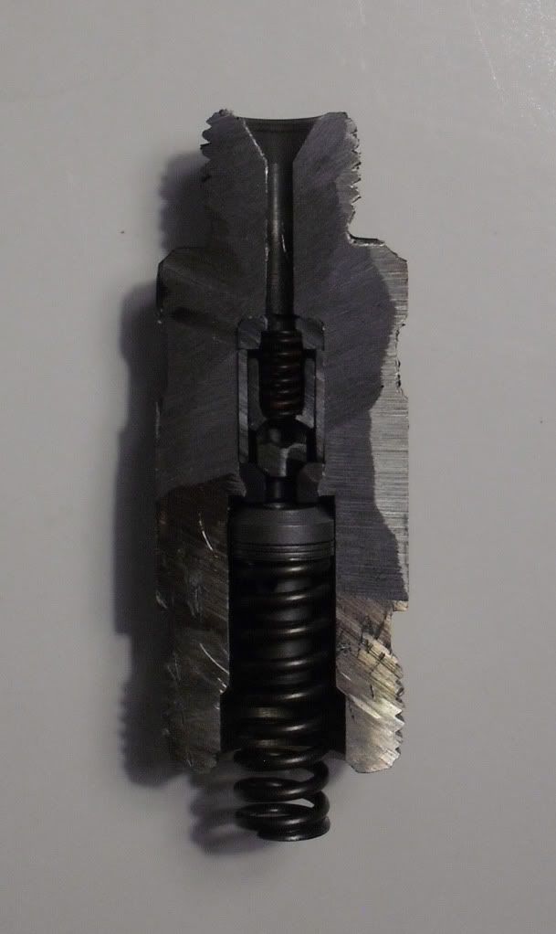
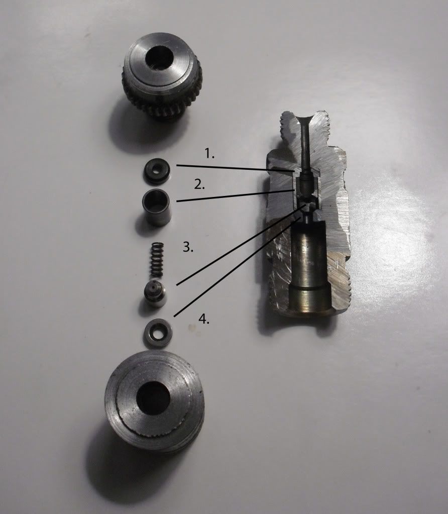
This is to show how a delivery valve holder operates.

All measurments are + or - .002"

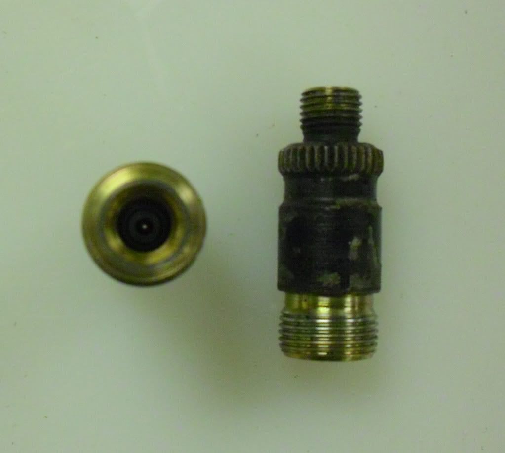
Unmodified holder, looks like the opening is too small to push fuel through untill you separate the parts.

CIMG6425.jpg


Holder on left split horizontally and parts pulled out. Holder on right everything is cut in half (missing spring on right).

CIMG6444.jpg


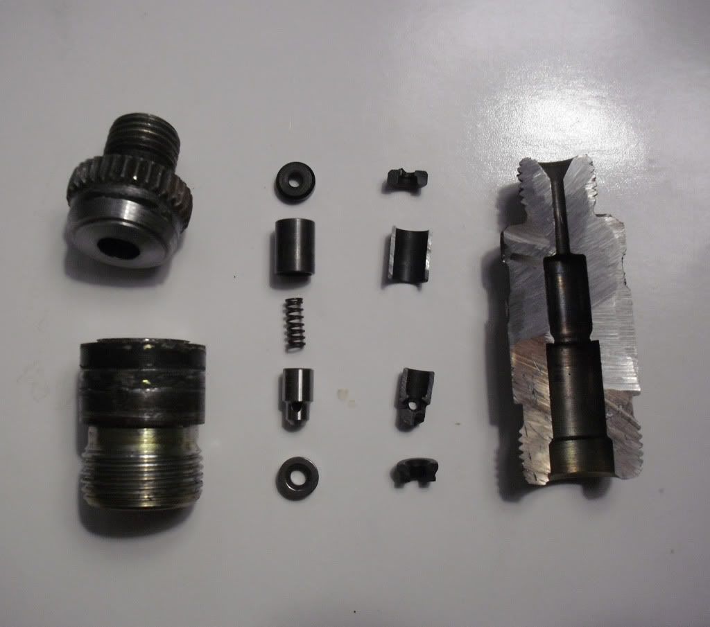
Sorry, but I dont know all the "officail" names of these parts, so I just used 1-4.
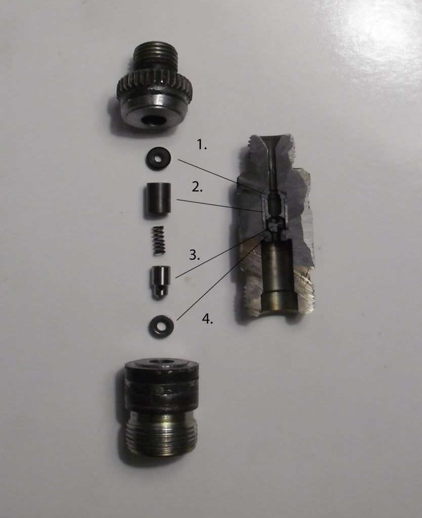
Parts assembled.
The fuel is first pushed up through #4 which has an opening of .120". It then is pushed up onto #3. #3 has a small .025" hole that goes straight through. This is the hole that most look at and think all the fuel is pushed through this small opening. That is a false assumption. The fuel pushes up on #3 and lifts it up off its seat on #4. #3 then has three holes for the fuel to pass through that are each .075" in diameter. The fuel then passes through the rest of #3 including through the spring. #3 moves up and down in #2 which is essentially just a sleeve. Next the fuel is pushed throught #1 which has a .100" diameter. Lastly the fuel is pushed through the rest of the holder which also has a .100" diameter.

As you can see the biggest resriction is the .100" passage. This design provides plenty of flow and thus does not need to be drilled out or have larger holders machined out.

meh2.jpg


another angle

meh.jpg
 
So with this I wonder why Bosch would make a holder with an enlarged opening, as far as the person is honest they (very well know pump shop) uses Bosch holders in there big build ups.......and no I don't have any, I still run stockers.

Good write up though and very interesting, much better that someone saying.....because I said so.

Jim
 
As you can see the biggest resriction is the .100" passage. This design provides plenty of flow and thus does not need to be drilled out or have larger holders machined out.

What is this statement based upon? Under a specific set of conditions I could agree with you, but under another set of conditions I wouldn't agree.

So which design would provide less pressure and flow restriction? A STRAIGHT pipe with 1" ID 1 foot long OR a pipe with 1" ID 1 foot long with FOUR 90 degree bends in it?
 
The DV holder is made to operate in two directions. To NOT allow the fuel to return into the delivery valve and plunger area with much force, and to allow the fuel to be pushed toward the injector without restriction. This is how they accomplish it. The fuel pushes up on #3 and can easily flow around the seat.

This is probably designed for street use pumps, so I can see how if you have over .100" lines on a competition truck only, then a free flow design might be superior.
 
ok so i ordered bigger DVs but i shoul djust run my stock holders ????? i think thats what im getting out of this
 
As I mentioned before, under certain conditions I would agree with your statement. For instance on a street truck that would see less than 4000 rpm I don't see any benefit. For trucks that see higher rpms, every restriction in the system needs addressed to get all that fuel into the cylinder in the short timeframe available.

Directly from the Bosch manual, "The valve body has a small bore the size of which is dimensioned to suit the application so as to achieve, firstly, the desired flow RESTRICTION and, secondly, to prevent reflection of pressure waves as much as possible."

Also remember, that the term "application" to which Bosch and Dodge designed these things to, is much different that what most of us here on CompD are using our trucks for. In the automotive industry, it is not common to take a fuel pump that was designed from the factory to move enough fuel for 160 hp and modify it to then deliver enough fuel for 1200 hp or more. My hats off to the Bosch engineers... :Cheer:
 
As I mentioned before, under certain conditions I would agree with your statement. For instance on a street truck that would see less than 4000 rpm I don't see any benefit. For trucks that see higher rpms, every restriction in the system needs addressed to get all that fuel into the cylinder in the short timeframe available.

Directly from the Bosch manual, "The valve body has a small bore the size of which is dimensioned to suit the application so as to achieve, firstly, the desired flow RESTRICTION and, secondly, to prevent reflection of pressure waves as much as possible."

Well said Jesse, I've had numerous Bosch techs and teachers tell me that style dv holder is for reducing the damaging force (shock wave) sent back through the injection line created when the injector closes.

Also, our shop uses the "open" style dv holder on pretty much all 13mm or larger builds. It's not the fuel gain we are targeting, our goal is keeping the entire injection system flowing like it should without any bottlenecks. Although we've seen as much as 50cc gains on 13mm pumps just by going from 6mm to 8mm dv's, so I'm sure the holder would hinder max fuel flow at some point.

Injecting 600ish cc's in as little as 12* engine rotation at 4000rpm and more demands a well flowing system. Power gains and pump longevity are key for our shop.

I have the parts gathered waiting to be tested, let's see what the test stand has to say.

I'm sure you've already thought of this, but if a sensor could be used (if it even exists) that could measure the pressure in the cavity above the dv (inside the holder) and then compare to another pressure sensor in the end of the injection line to see what, if any, pressure changes could be noted. It would be more beneficial to know in my opinion than a fuel delivery difference.
 
Last edited:
Back
Top