
You are using an out of date browser. It may not display this or other websites correctly.
You should upgrade or use an alternative browser.
You should upgrade or use an alternative browser.
Project Leftovers: The Rise of Frankenstein
- Thread starter Big Blue24
- Start date
Big Blue24
Comp Diesel Sponsor
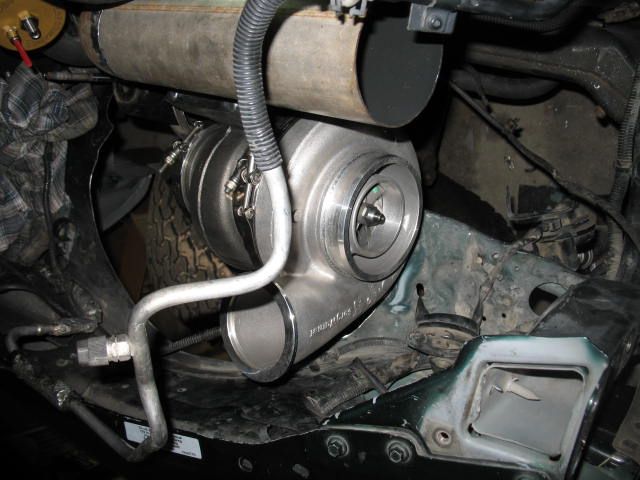
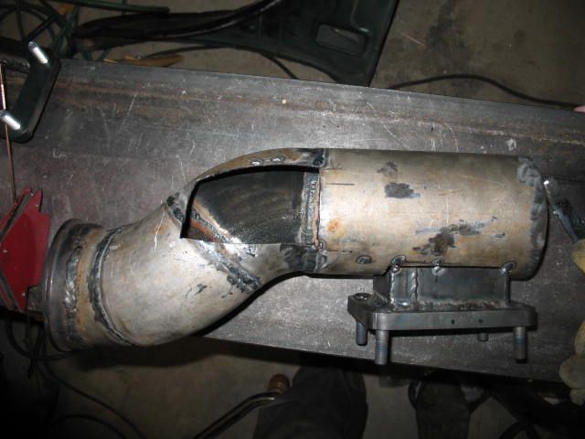
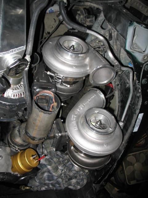
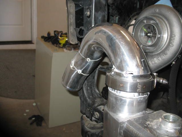
Todd went head-first in fabricating the hotpipe to feed the two S475's from the GTX4202's exhaust outlet.
First attempt, Todd started with a long straight that came up toward the factory oil filter.
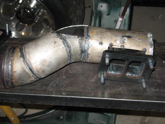
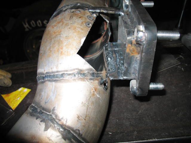
Next was the fabrication of the T-6 flanges that feed from the single primary log.
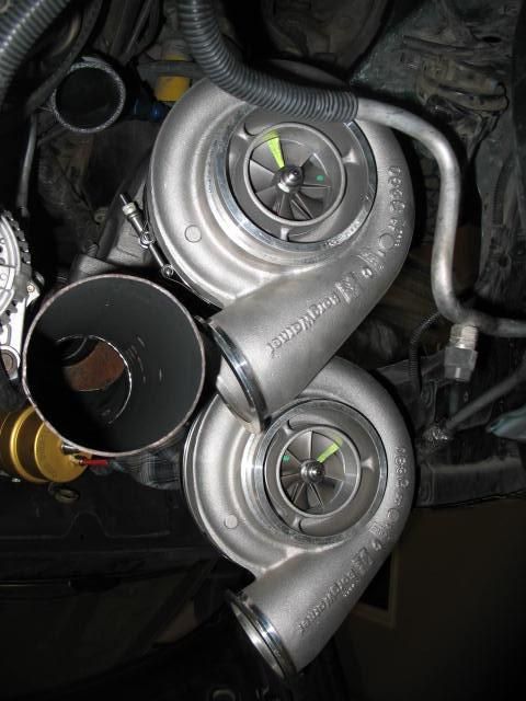
Then mock-up of the first S475:
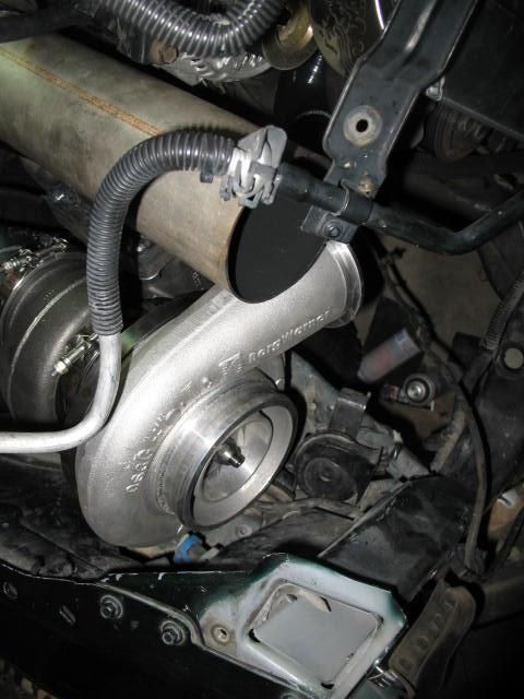
Then mock-up of the 2nd S475:
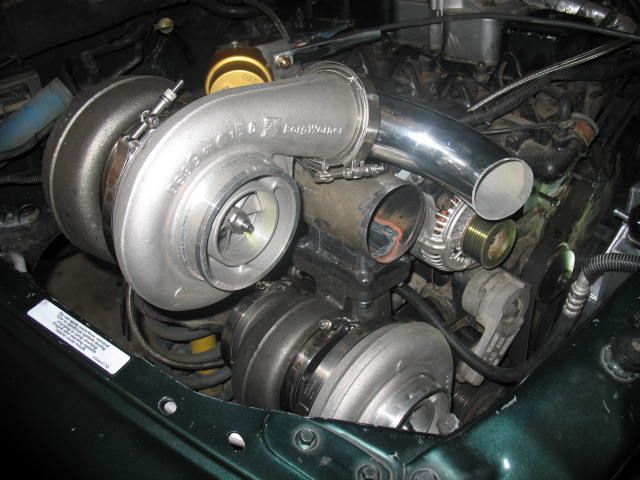
All (3) turbos mounted:
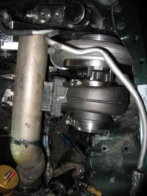
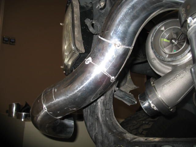
Then after realizing there wasn't sufficient room to mount the oil drain lines, the upper S475 had to be relocated:
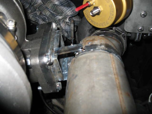
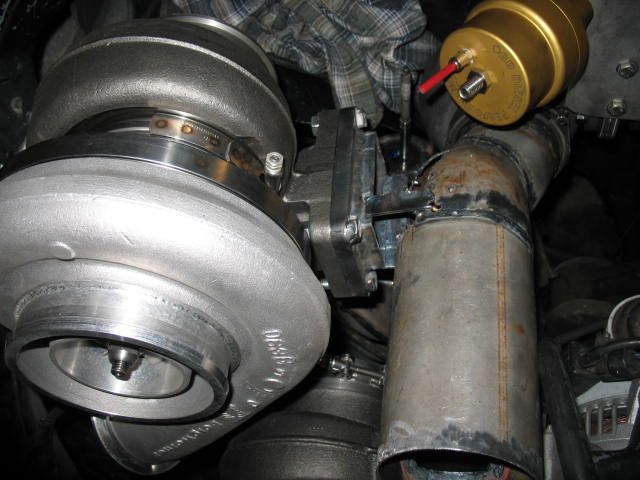
All three turbos mounted and now there is plenty of room for the oil drain on the upper S475, however, the hood wouldn't close. So the hotpipe was chopped up one more time:
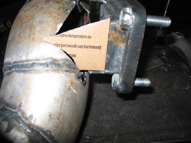
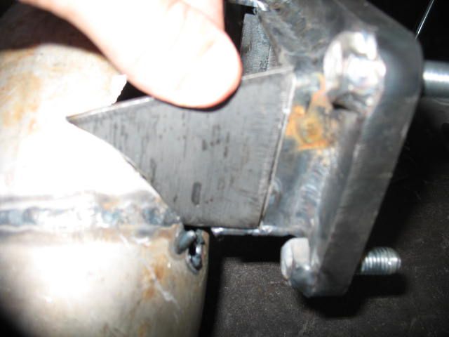
One thing we've both learned as beginner fabricators, cardboard is much easier to shape and fit than raw steel, so use cardbard for complicated angles and then use it as a pattern for the steel finished piece.
First attempt, Todd started with a long straight that came up toward the factory oil filter.
Next was the fabrication of the T-6 flanges that feed from the single primary log.
Then mock-up of the first S475:
Then mock-up of the 2nd S475:
All (3) turbos mounted:
Then after realizing there wasn't sufficient room to mount the oil drain lines, the upper S475 had to be relocated:
All three turbos mounted and now there is plenty of room for the oil drain on the upper S475, however, the hood wouldn't close. So the hotpipe was chopped up one more time:
One thing we've both learned as beginner fabricators, cardboard is much easier to shape and fit than raw steel, so use cardbard for complicated angles and then use it as a pattern for the steel finished piece.
Big Blue24
Comp Diesel Sponsor
make sure to knife edge those divided flanges or they will erode, better yet knife edge the exhaust housings and make the flanges undivided
Have you had issues with divider/flange erosion on the second turbine(s) or atmospheric turbo stage? I've seen plenty of eroded dividers on manifold turbos but can't recall seeing them on the down stream exhaust housing inlets.
Something for Todd and I to look into for sure, thanks for the suggestion!
Big Blue24
Comp Diesel Sponsor
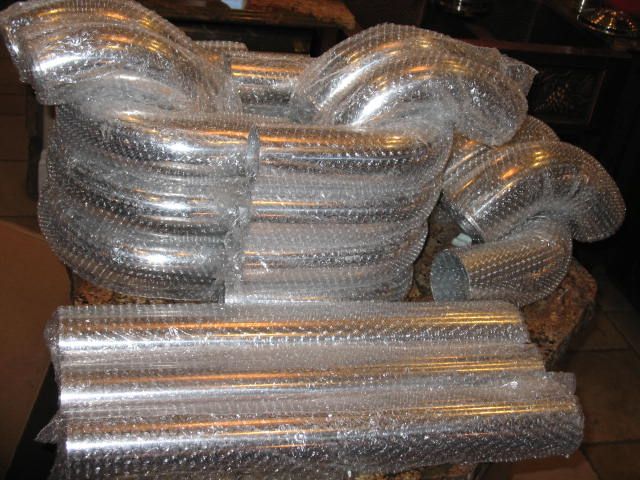
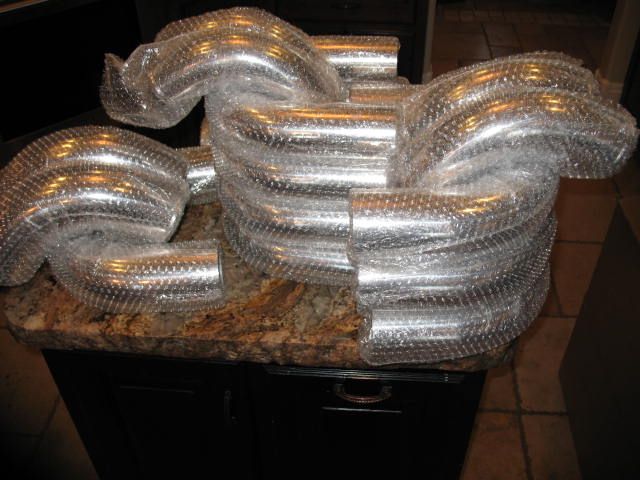
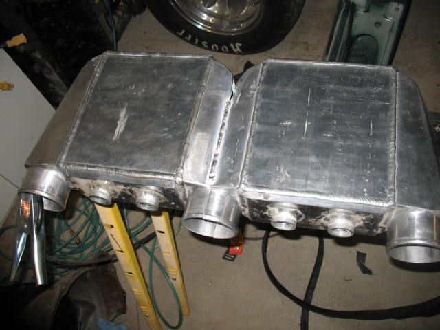
A large shipment of 3.5" aluminum tubing arrived from Frozen Boost, it's the cheapest aluminum 16 gauge pipe we could find. Time to get started on the heavy plumbing and cooler fabrication:
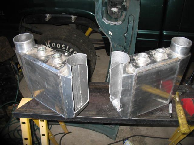
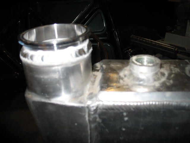
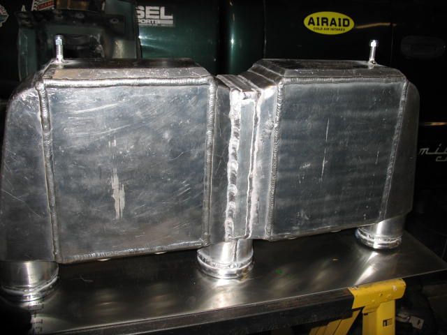
The next step was getting an intercooler large enough to handle the flow of (2) S475's or roughly 200 lbs per minute or 3000+/- CFM. Todd had (2) old and lightly used Frozen Boost water/air coolers sitting on the shelf so keeping true to the theme, it was time to merge them into something useful.
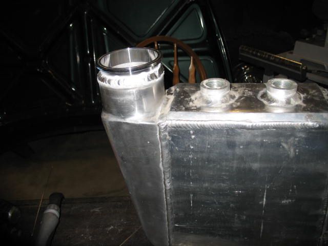
The first step was to open them up using a 4.5" hand grinder with a cutting wheel (no access to a band saw).
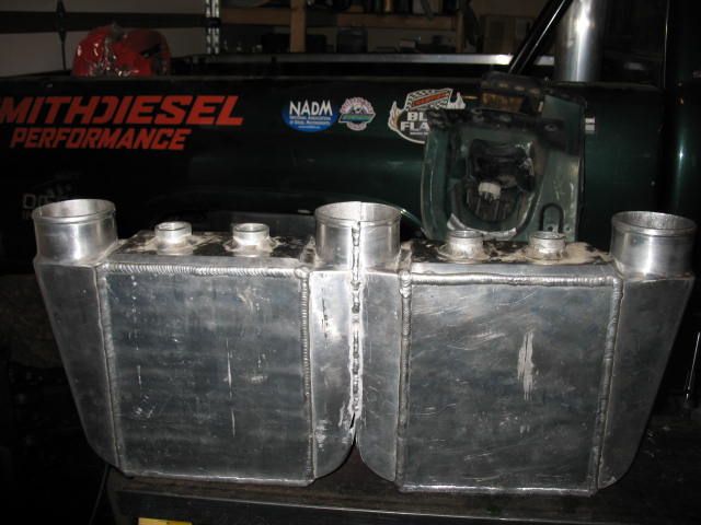
Todd is still new to TIG welding aluminum but slowly getting better:
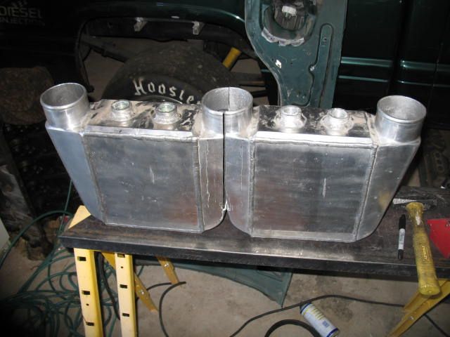
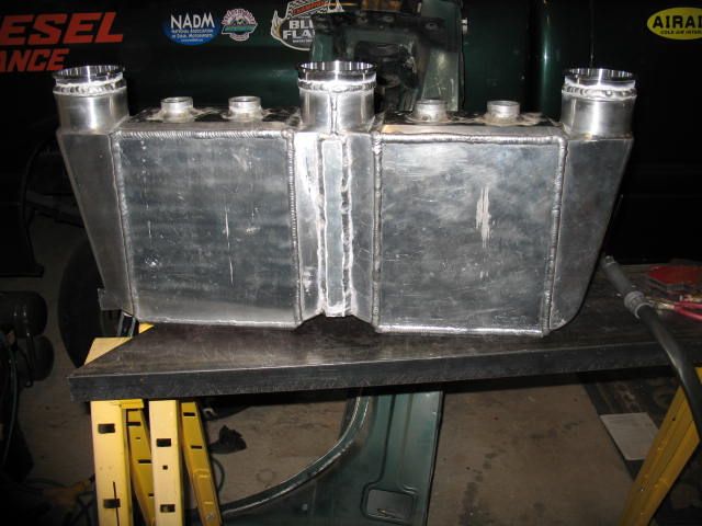
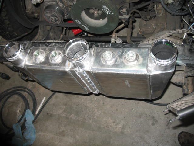
In case you haven't picked up the concept from the pictures, each separate S475 will blow compressed air into one of the outer inlet tubes, the boost will flow across the two coolers and merge into the center outlet pipe. Intercooling between stages is important on this build for (2) reasons: it aids in overall system efficiency by increasing charge air density prior to the second stage of compression & it decreases the thermal fatigue load on the GTX's compressor wheel which could overheat and fail if ran hard while being fed 350+ degree charge air vs. 120-130 degree charge air it will receive thanks to intercooling.
Due to the potential high boost these coolers will receive, some additional bracing was added to reinforce the merged cooler connection.
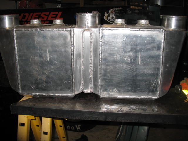
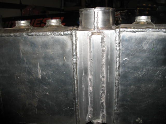
V-bands were also added to prevent blown charge air cooler boots/hoses.
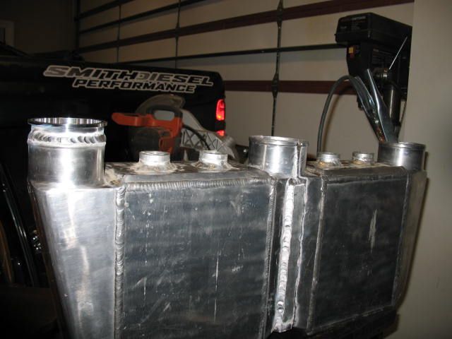
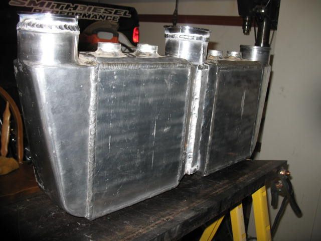
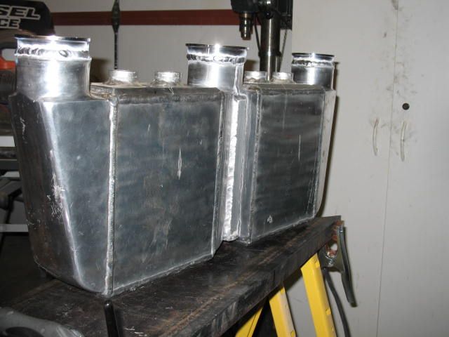
All finished:
The next step was getting an intercooler large enough to handle the flow of (2) S475's or roughly 200 lbs per minute or 3000+/- CFM. Todd had (2) old and lightly used Frozen Boost water/air coolers sitting on the shelf so keeping true to the theme, it was time to merge them into something useful.
The first step was to open them up using a 4.5" hand grinder with a cutting wheel (no access to a band saw).
Todd is still new to TIG welding aluminum but slowly getting better:
In case you haven't picked up the concept from the pictures, each separate S475 will blow compressed air into one of the outer inlet tubes, the boost will flow across the two coolers and merge into the center outlet pipe. Intercooling between stages is important on this build for (2) reasons: it aids in overall system efficiency by increasing charge air density prior to the second stage of compression & it decreases the thermal fatigue load on the GTX's compressor wheel which could overheat and fail if ran hard while being fed 350+ degree charge air vs. 120-130 degree charge air it will receive thanks to intercooling.
Due to the potential high boost these coolers will receive, some additional bracing was added to reinforce the merged cooler connection.
V-bands were also added to prevent blown charge air cooler boots/hoses.
All finished:
 op:
op:Thanks for all the kind words and good suggestions. I have been spending every free moment I have in the garage trying to get it built. I have been getting up very early so I can get in an extra hour in the morning. Am starting to get burnt out a bit. Today I was doing some stuff under the truck on the creeper and fell asleep. I was just staring up thinking about how I was going to route some stuff and then I woke up. Anyone ever done that before? I am going to take a day off from it and hope to rejuvenate myself and hit it hard again next week.
Thanks for all the kind words and good suggestions. I have been spending every free moment I have in the garage trying to get it built. I have been getting up very early so I can get in an extra hour in the morning. Am starting to get burnt out a bit. Today I was doing some stuff under the truck on the creeper and fell asleep. I was just staring up thinking about how I was going to route some stuff and then I woke up. Anyone ever done that before? I am going to take a day off from it and hope to rejuvenate myself and hit it hard again next week.
ive done it before, actually kinda relaxing laying under a truck lol
CorneliusRox
Seasoned Rookie
Are you going to have two separate systems for each of the water to air coolers? It might be hard to get even supply flow between the two with one pump and a t-fitting. I suppose it wouldn't matter too much if they weren't perfect though. Just curious!
Big Blue24
Comp Diesel Sponsor
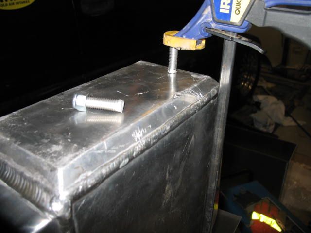
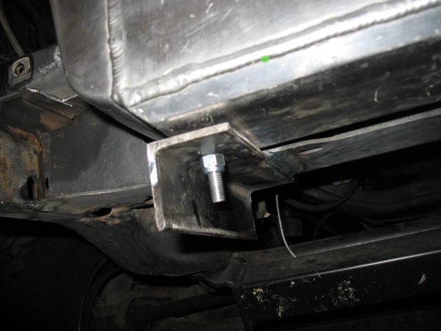
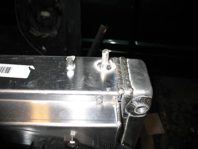
In order to mount the water/air cooler, studs needed to be added to the bottom. Todd started with some aluminum round stock and die to create aluminum threaded rod.
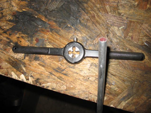
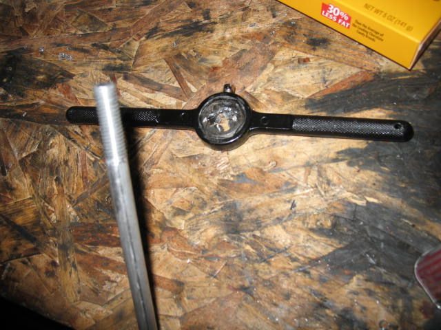
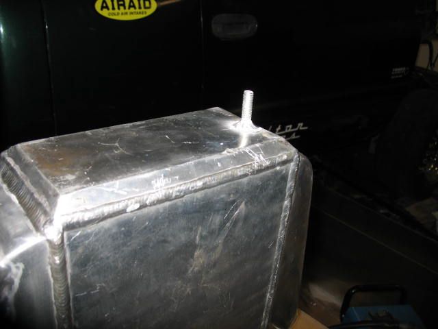
Then the aluminum studs were clamped into place and tig welded:
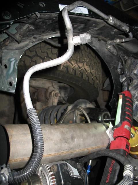
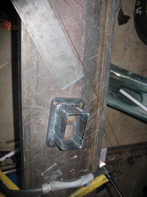
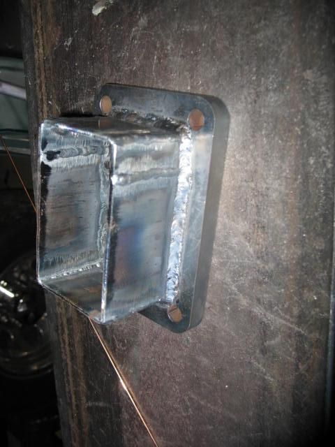
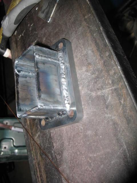
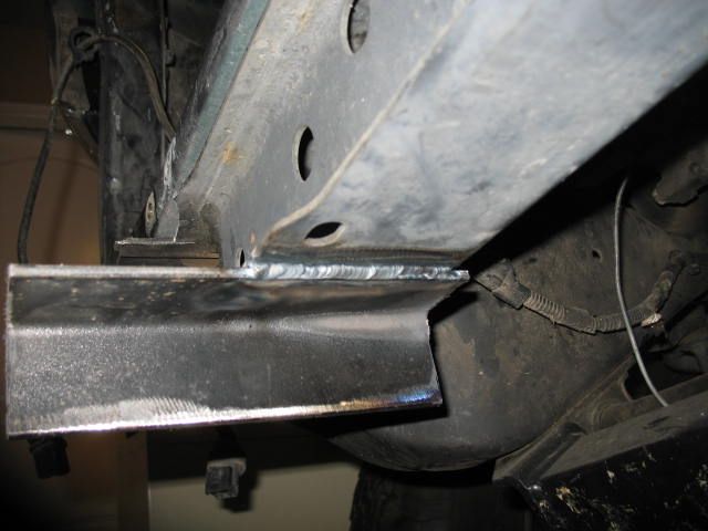
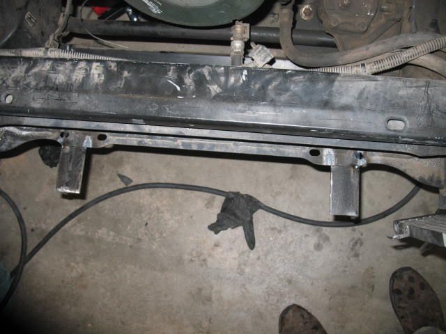
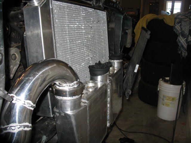
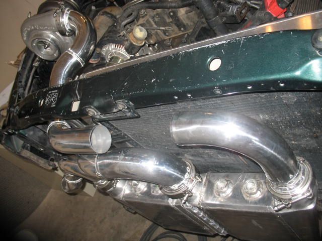
Next brackets were welded to the truck to accept the water/air cooler in place of the stock air/air intercooler (CAC).
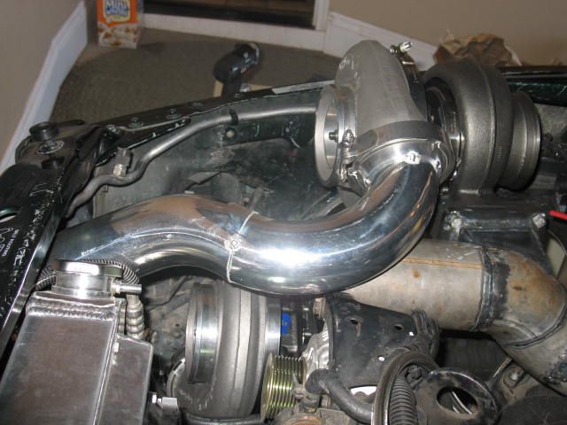
After the cooler was fitted into place, the complex plumbing work began.
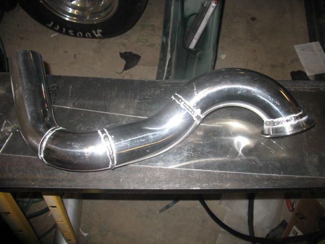
Around the core support on the front end:
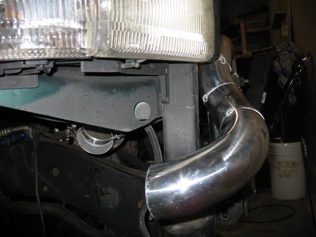
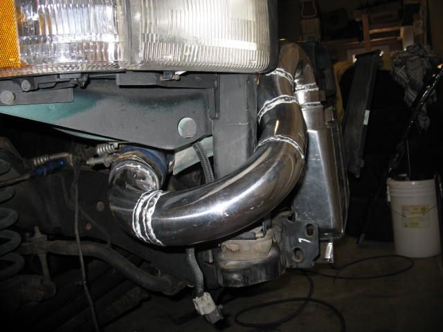
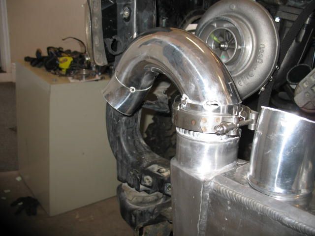
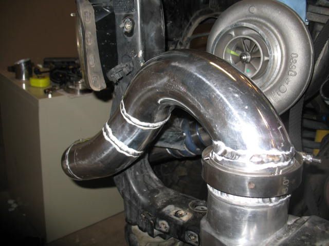
One S475 primary turbo coldpipe completed:
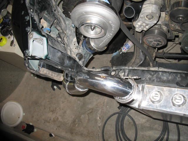
V-banded for reliability during high boost runs.
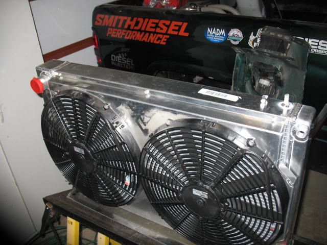
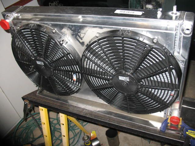
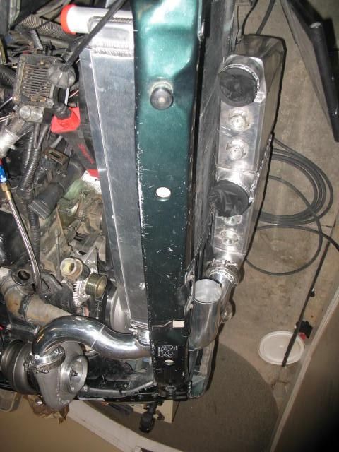
Next Todd worked on mounting the radiator:
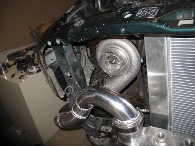
With the radiator in place, Todd then worked to route the charge pipe for the second S475 into the other end of the water/air cooler.
Then the aluminum studs were clamped into place and tig welded:
Next brackets were welded to the truck to accept the water/air cooler in place of the stock air/air intercooler (CAC).
After the cooler was fitted into place, the complex plumbing work began.
Around the core support on the front end:
One S475 primary turbo coldpipe completed:
V-banded for reliability during high boost runs.
Next Todd worked on mounting the radiator:
With the radiator in place, Todd then worked to route the charge pipe for the second S475 into the other end of the water/air cooler.
Last edited:
Big Blue24
Comp Diesel Sponsor
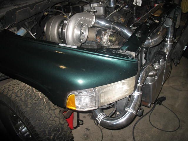
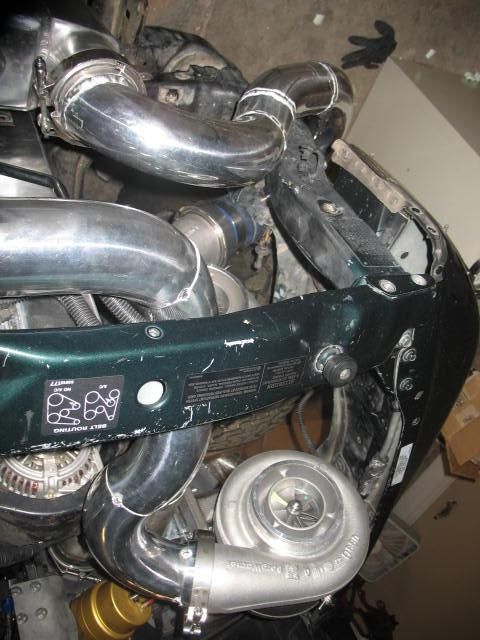
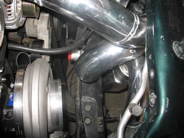
Some final welding on the earlier tacked sections to ensure all movement and pulling/alignment changes would occur prior to the final cuts and fitted section.
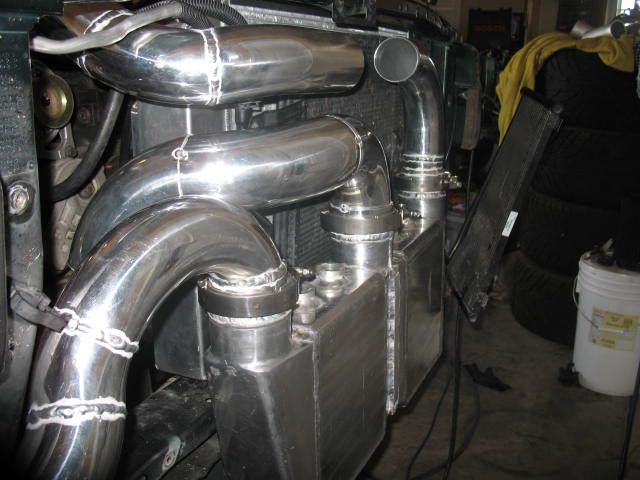
It's a tight fit but Todd made it all work:
Newdieselguy
Captain sleeps alot
Keep up the awesome work, hopefully you guys get everything working good and get voted in.