
You are using an out of date browser. It may not display this or other websites correctly.
You should upgrade or use an alternative browser.
You should upgrade or use an alternative browser.
Dicking Around . .
- Thread starter BC847
- Start date
12valve95
Comp Diesel Sponsor
X2. You can actually remove the beginnings of a crack and not even know it by removing stress risers.
Is it a precision job? Obviously you cant just hack at it like an idiot, but can you just be freehand on the same plane or does it need to be more precise?
I am gearing up to rebuild a 12 Valve from bare block up so I might as well do this while I am in there if it is possible for me to do.
Block has 247,000 on it so anything I can do to keep it living its new life, I am in.
Pretty much any jagged edge on cast iron is a stress riser. In other words, it's easier for a crack to start there because forces are concentrated into focused areas. The name of the game is to smooth things out so forces are shared over surface areas equally.
BC847
New member
I used a 4.5" hand-held angle-grinder, a pneumatic die-grinder with a small diameter burr, the nose of a belt-sander, and open-mesh sanding-cloth.Is it a precision job? Obviously you cant just hack at it like an idiot, but can you just be freehand on the same plane or does it need to be more precise?
The primary goal being to not hit the danged main-bearing machined surfaces.
")
- Cut running the length of the object. Not across it (cutting across introduces potential stress-risers). Round any and all sharp corners.
- Safety-glasses and a mask are pretty cool.
BC847
New member
OK. Here we go . . . .
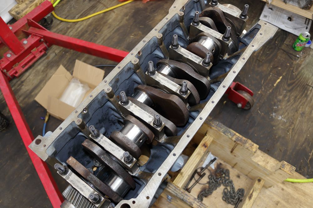
Slathered-up the 24v tappets with assembly-lube and slid those boys in there:
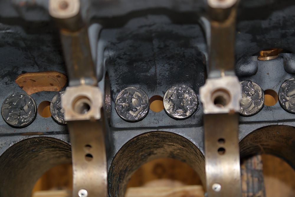
Installed new piston cooler nozzles:
Installed the upper main bearing halves insuring that the lube-oil passages met appropriately:
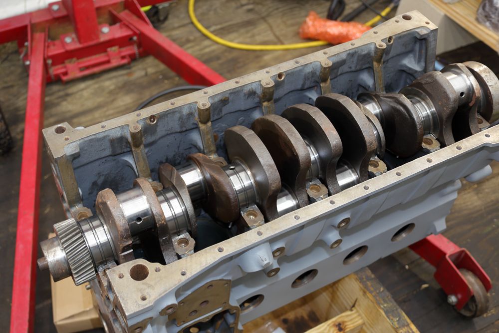
Set that heavy-assed crankshaft in there. (In hind-sight, I should have at least cleaned up the forging-flash and stress-risers before having it balanced):
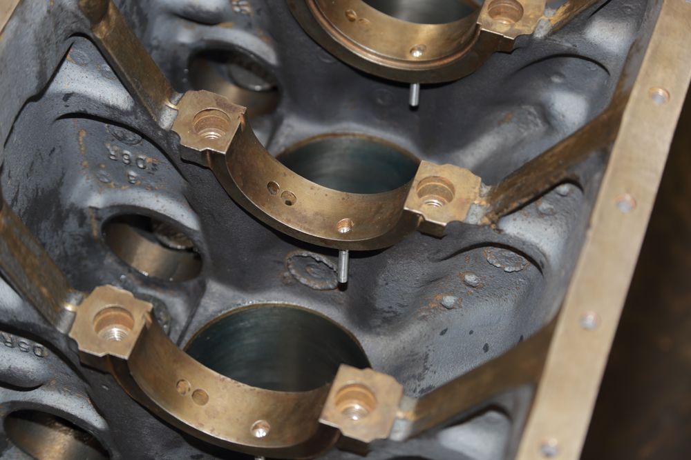
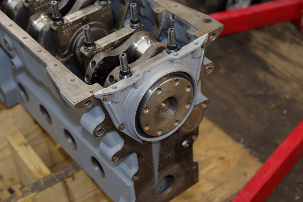
Installed the main bearing caps with the lower main bearing halves and temporarily pulled the stud-nuts up to 40ish ft/lbs:
Then test-fit the girdle:
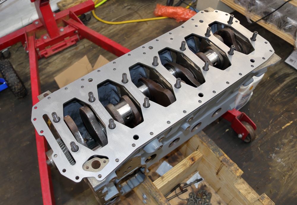
Then removed the stud-nuts, slathered them with the ARP squeez'ns and, via multiple steps, pulled them up to spec:
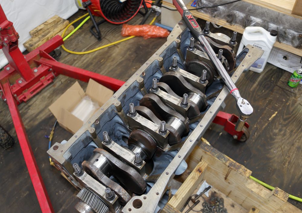
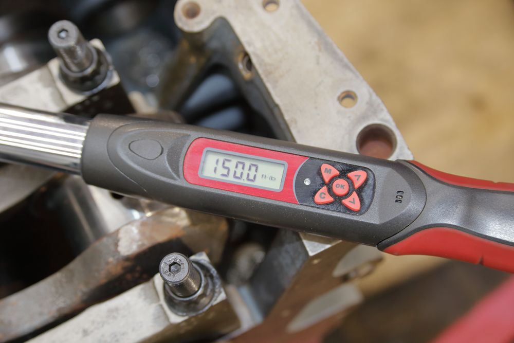
150ft/lbs in this application:
We'll see, huh?
Slathered-up the 24v tappets with assembly-lube and slid those boys in there:
Installed new piston cooler nozzles:
Installed the upper main bearing halves insuring that the lube-oil passages met appropriately:
Set that heavy-assed crankshaft in there. (In hind-sight, I should have at least cleaned up the forging-flash and stress-risers before having it balanced):
Installed the main bearing caps with the lower main bearing halves and temporarily pulled the stud-nuts up to 40ish ft/lbs:
Then test-fit the girdle:
Then removed the stud-nuts, slathered them with the ARP squeez'ns and, via multiple steps, pulled them up to spec:
150ft/lbs in this application:
We'll see, huh?
12valve95
Comp Diesel Sponsor
I used a 4.5" hand-held angle-grinder, a pneumatic die-grinder with a small diameter burr, the nose of a belt-sander, and open-mesh sanding-cloth.
The primary goal being to not hit the danged main-bearing machined surfaces.
- Cut running the length of the object. Not across it (cutting across introduces potential stress-risers). Round any and all sharp corners.
- Safety-glasses and a mask are pretty cool.
Awesome, thanks for the info!
Watching this build, like the girdle!
Are you using metal oil squirters?
BC847
New member
Yes. Aluminum with the slightly oversize bore.Are you using metal oil squirters?
BC847
New member
Nope. All that checked out good. Besides, in this case, you're only going 20ft/lbs over stock.Did you have to line bore your block to run the main studs?
It was a slow day as far as engine building goes. Bits and pieces, nuts and bolts.
Speaking of bolts: I've chased the threads on all the bolt-holes of the block so, took the time to chase the threads of the actual bolts themselves. It was tedious at best. :x-out:
Anyhoo, did a final cleaning of the block's main lube-oil gallery and plugged the ends. Installed Speedy-Sleeves on both ends of the crankshaft:
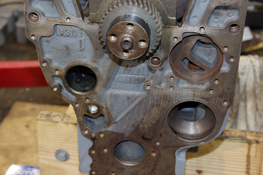
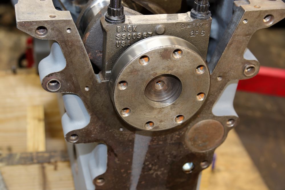
Installed the rear crankshaft seal and it's associated housing:
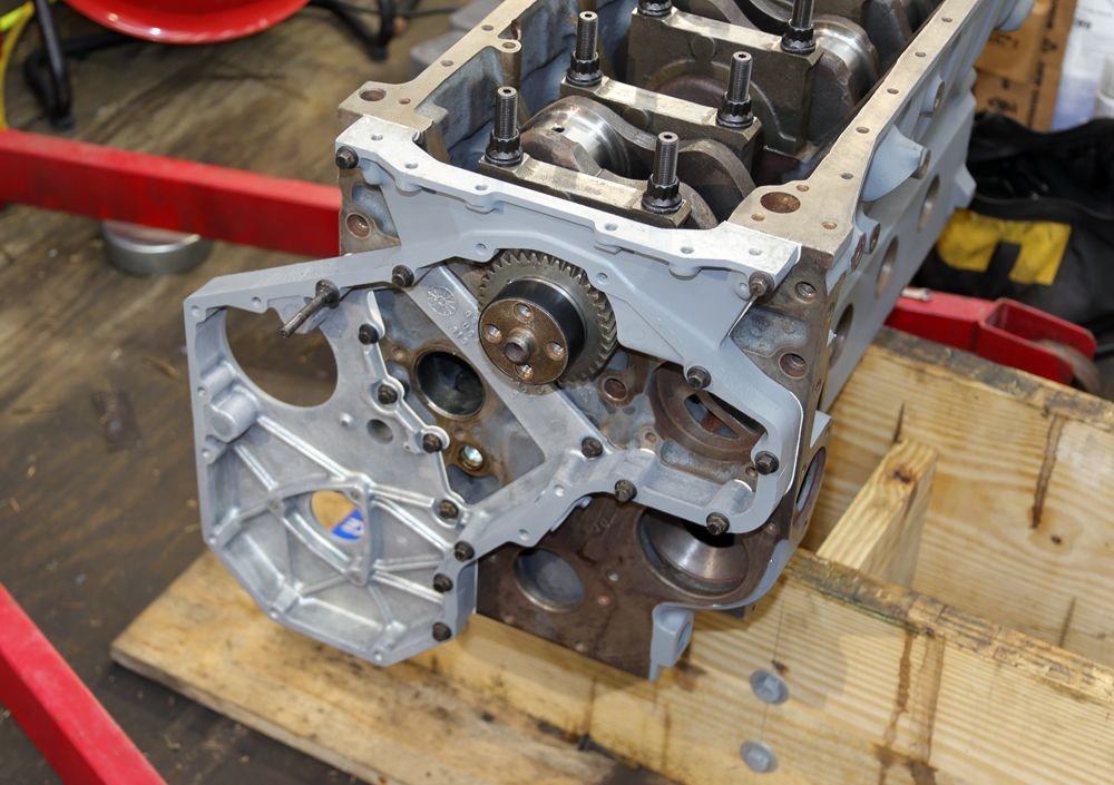
And finally, installed the front gear-case. I went ahead and torqued all the case-bolts just to hold things square for now. BLUE Loc-Tited and torqued those internal gear-case to block bolts:
Last edited:
I wouldnt unless you have access to a scale to make sure they are all equal, and then, what benefit? Has anyone else BTDT?I'm wrestling with, at least cutting off the bulk of the connecting-rod's, main-bearing cap's balancing pad for the reduction of reciprocating mass.
Thoughts?
BC847
New member
I have all that required to do the work including re-balancing the rods.I wouldnt unless you have access to a scale to make sure they are all equal, and then, what benefit? Has anyone else BTDT?
In my head: It requires energy to put mass in motion. In this case, we're talking about parasitic power losses. The lower the reciprocating mass, the less power required to get what's left moving. Said free'ed power can be used elsewhere.
It seems I recall some rule-of-thumb that suggests for every two pounds of reciprocating mass removed, @ 4000 engine rpm, there's approximately 20hp to be gained. At 5000 engine rpm, perhaps 40hp.
I won't regularly be spinning my heap to 4K and above but, it only takes, what, 0.001 second to best my competitor?
Last edited:
biggy238
Active member
I knocked a bit out of the underside of my stock pistons to get them all to the same weight. I think the carillo's were all nearly the same weight, but I did weigh them with a food scale and a jig I made. Weighed the wrist pins also.
It's my opinion that this engine is smoother when cruising than the other two B's I've owned, but obviously just SOTP opinion.
Sent from my motorola one action using Tapatalk
It's my opinion that this engine is smoother when cruising than the other two B's I've owned, but obviously just SOTP opinion.
Sent from my motorola one action using Tapatalk
BC847
New member
Had to take a break and do work that actually pays for this mess. :bang
Back at it this evening finds my CDO has been worrying the crap out of me. I gave in. :doh:
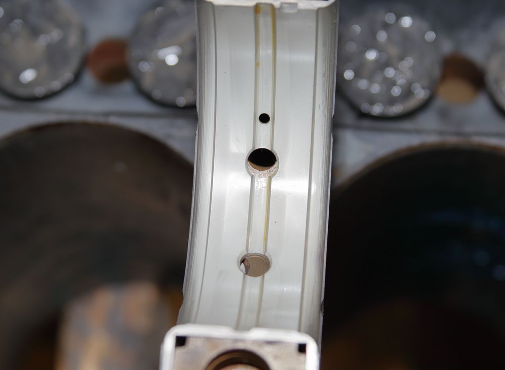
While the connecting rod beams weren't bad (I guess), I went ahead and blended those surfaces. Same for the small ends:
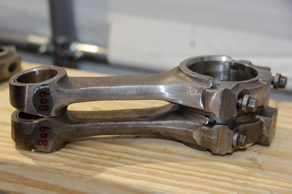
Cut a big chunk of metal from the balancing pad on the big end. Blended all that as well:
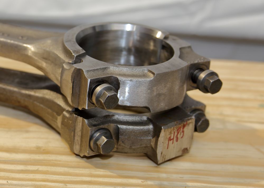
I plan on balancing the rods and pistons in the morning (if I'm lucky enough to wake up ).
Back at it this evening finds my CDO has been worrying the crap out of me. I gave in. :doh:
While the connecting rod beams weren't bad (I guess), I went ahead and blended those surfaces. Same for the small ends:
Cut a big chunk of metal from the balancing pad on the big end. Blended all that as well:
I plan on balancing the rods and pistons in the morning (if I'm lucky enough to wake up
).Red Sleeper
Active member
What was the before and after measured weight of the con rods?
I’ve always known a phrase, “blue print, polish, and balance an engine.”
Blueprint meaning measurements of necessary components.
Polish meaning polishing of rotating components for less drag and rotating weight.
Balance for weighing necessary components to achieve a perfectly balanced rotating assembly.
Your thread reminds me of the feller who machined off most of the counter wright in his 12v crankshaft. Somewhere there is a thread about the topic. He followed through and ran the crank despite the skeptical feed back.
biggy238
Active member
I went back to re-read what he had done when I assembled my engine. Seems like a dirt-bike accident did him in.What was the before and after measured weight of the con rods?
I’ve always known a phrase, “blue print, polish, and balance an engine.”
Blueprint meaning measurements of necessary components.
Polish meaning polishing of rotating components for less drag and rotating weight.
Balance for weighing necessary components to achieve a perfectly balanced rotating assembly.
Your thread reminds me of the feller who machined off most of the counter wright in his 12v crankshaft. Somewhere there is a thread about the topic. He followed through and ran the crank despite the skeptical feed back.
Sent from my motorola one action using Tapatalk