VE Tech

There are things you can improve on. As soon as a get another pump, I have a pump case I modded a few years ago and I modded a junk head assembly to learn a few things. I believe I have found a couple ways to help higher rpm fueling for our 12mm heads. Which, if it does help, would help 14mm longevity.
 
Jon, did you ever get around to actually doing that pump case? I remember on 1stgen you had plans to and there was a huge discussion on there and DTR about it. Then the vein pump modification discussion came up and the duel feed VE idea. I hoped the one guy who was talking about sealing the H&R from the case and feeding the H&R it's own fuel via one of those belt driven pumps was going to move on with the idea but he switched to a pPump (the smarts idea). Captain Chrysler, I think was his screen name?

Reading back in the 1stgen archive's gives a guy lots of ideas, yet these things are so out dated no one wants to mess with them much. I hope this thread stays alive and something comes of it.
 
There is a guy on here who did the bypass feed.

I have the case but all of the hard parts I've slowly given away.
 
I beleive that case pressure is only an issue because the vane pump regulating valve opens at higher rpms. Thus not allowing the case to keep a steady pressure. Once the regulating valve opens it reduces the pressure significantly.
My case-pressure gauge shows differently.
The case-pressure regulator is just like any regulator. In our application, it starts venting when the case-pressure reaches the point where it overcomes the regulator's spring.

It does not cause a drop in case pressure. Its effect is to limit it, (within its venting capabilities). It does not cause any instabilities in the case-pressure (steadiness as you put it).

Along with the case overflow-orifice (overflow-valve in a p-pump), and the IP's input shaft speed, the regulator works so as to have a rising case-pressure so as to stroke the dynamic-timing device so as to arrive with an appropriate advance in injection-event timing.


IIRC, most of those who've fed the H/R with an external pump ultimately ended up with a broken cam-plate, etc.
 
Last edited:
Some pumps it seems from the factory are 1/2 turn from runaway and max out at ~150 hp, others are 3 turns from runaway and hit 250 (all 12mm). Why? is there some fulcrum lever geometry differences that make a difference?
One must first understand how the fuel is controlled by the IP.

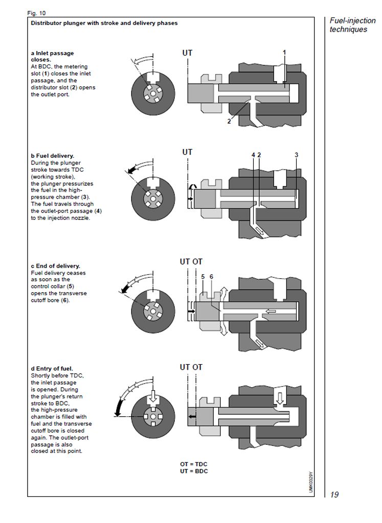
Along with passages to move fuel into the H/R, and then to the DVs, there's a passage though the rotor that flows fuel back toward the case. It terminates at a spill-port that's covered by the control-collar. All the throttling linkage including that of the AFC eventually links to the control-collar. Want more fuel? Move the control-collar so it covers the spill-port more, Want less fuel? Move the control-collar so it uncovers the spill-port more.

Notice I say "More" in each case.

Understand that while the rotor is moving in and out of the head, it's also moving back and forth through the throttle-collar. My point is that the throttle-collar does not cover and uncover the spill-port in an instantaneous fashion (snap open / snap closed). More often than not, when coming off the throttle, the fuel is not stopped completely. It's simply reduced.

fuel-delivery_zpsbd580eed.jpg


Getting to your question, a run-away situation is a result of having the fuel control linkage (indexing, main fuel screw, etc) set so that the minimum fueling is such that it allows enough fuel flow so as to overcome any of the engine's resistance to rotation (fine-print goes here).

The above being: the control-collar is not covering the rotor's spill-port enough at the end of the rotor's in and out stroke.

Make sense? It's been my experience the throttle's indexing sets the stage, and is complimented via the main fuel-screw. Pushing it till you're only able to set the engine's idle via the main fuel-screw is about as far as you'll be able to go without run-away.
 
Last edited:
IIRC, most of those who've fed the H/R with an external pump ultimately ended up with a broken cam-plate, etc.

Mine didn't tie up till I installed the 4mm can plate, it had a ton of wot stand time and quite a bit of pounding on the truck
 
Something I noticed while having several pumps tore apart and putting one of them back together, is different length timing pistons, obviously to control the amount of timing advance. It then dawned on me, rather than buying a timing spacer, doing some math and modifying the length of the piston would be a cheap easy way to get the amount of advance you would like to have.

There will come a point, where too much dynamic timing will start to be hard on the pump and/or reduce fuel quantity due to the discharge ports not lining up properly. I would think for this reason a 14mm head would be best used with little or no dynamic timing. I wonder if the 4mm cam plates that never seem to work out are a result of discharge port misalignment.
 
Timing has no affect on the pump, and it doesn't change the relationship to the ports inside the pump.... it does nothing more than change the timing of when it injects in relationship to the engine.
 
Dynamic timing changes the alignment of the discharge ports in the rotor vs the head during injection. It rotates the roller carrier, therefore changing where the start of injection is in the rotors rotation. The shorter piston I used in a pump tonight allowed the roller carrier to rotate 7*, allowing 14* of dynamic timing.
 
Thought this may be of interest to some, was trying to figure out the flow volumes of the vane pump vs the piston pump, and its relationship to case pressure, did up a bit of a spread sheet.

Using the measurements of 2 of the pumps I have here and measured the orifice sizes of the pump regulator I worked out the flow rates of each pump at 100% then the flow rates of the orifice, and the resulting rise in case pressure. I found it interesting and after checking the results others have had with measurements they have found in real life testing it is probably not one hundred percent accurate but it represents it close enough to get a visual of whats happening.

The measurements of the pump flows are pretty close as they are made using exact specs and formulas, the orifice flow is close but from what I can tell there is no way to 100% calculate orifice flow as there are so many variables.

Pump flow graph.jpg

RPM bottom
Case PSI right
Flow in GPM left

I have set the piston pump out put at 80% to reflect what would happen at full throttle. Can understand that it is all not that linear with governor control etc but you get the idea.

The base pressure is set at 60/70psi or so by regulator valve so in reality case pressure wouldn't dip as low as shown in the graph but it was hard enough working it out this far. You can see that at the lower revs and with a high percent piston flow due to large injectors that the vane pump doesn't flow enough to keep up with flow of piston pump and the orifice flow potential. you can reduce the size of the orifices but that cause a huge increase in case pressure at high rpm.

If there was a way to better regulate case pressure rather than the fixed orifice design the improvements could be substantial. I haven't thought of a way without using a electronic control. Maybe a better designed pilot relief valve and using a rising rate reg on the return line you could use a boost pressure signal to increase back pressure on the pilot valve and then that would increase the pilot valve relief setting?

The vane pump has 2GPM flow at 3500rpm (engine) its just lost due to the orifice used to supply the dynamic case increase. Any way food for thought.
 
That dip is overcome by proper AFC tuning.

From real world experience... using my 15 psi kit... with 80psi of idle and 200 psi at wot with ksb on.

With an afc delete, I can drop my case pressure to about 20psi. With PROPER AFC SET Up. I get no more than 20-30 psi worth of drop anywhere in the system.

That is with 6ish psi of inlet at wot (15 at idle/no load)
 
Case pressure issues really is not by any means as big of a problem as folks make it out to be. Nor do they need stupid amounts of inlet pressure on a 12mm pump.

In fact the highest hp ever made with a 12mm on fuel only was at 12 psi of inlet at wot.
 
If case pressure is not an issue what do you think possible areas of improvement could be? Not being smart just want to get an idea on where to look.
 
Managing to get the h/r assembly to move more fuel..... The reality is, the entire pump works within its own parameters (the abilities of all the pieces are equal).

Simple things can be done for the "lacking" areas (timing dropping, afc not regulating all that well, etc...).

The MAIN issue is.... it has a single 12mm plunger feeding 6 injectors.


Fine tuning things and the best tuning for a given set up is what will make more power with a ve.


THERE ALSO MAY BE A LOT OF ADVANTAGE (I'VE NEVER TRIED IT) IN MAKING THE INTERNAL PASSAGES MORE EFFICIENT. something like a port and polish type method.
 
Fact is there is only 1 plunger feeding every power stroke of a PPump engine as well. Its not like a VE automatically has 1/6 the potential. The limit is not the plunger size, its the dynamics of feeding each cylinder.

Its cool to see the VE stuff progressing as it still is.
 
Fact is there is only 1 plunger feeding every power stroke of a PPump engine as well.

I agree.

Fill time/ quality on the VE becomes more important which is why I was focusing on improving the case pressure issue.

The difference in flow of a orifice of 100thou from 100psi to 200psi is over 1gpm so for me having the highest available case pressure available to supply filling is important, if it can maintain dynamic timing.

The thing is people focus on the vane pump as the weak link when in reality it is capable of flowing as much as 2 walboro lift pumps at 3500rpm engine speed. where is that flow going?

"THERE ALSO MAY BE A LOT OF ADVANTAGE (I'VE NEVER TRIED IT) IN MAKING THE INTERNAL PASSAGES MORE EFFICIENT"

I know from learning the flow calculations there is a percentage increase in flow of orifices or passages by chamfering the inlet and out let relative to the internal diameter. Kind of like holley carb jets, and why they say don't mess with em because the flow calibrated to the inlet outlet and internal diameter.

If you chamfer the inlet and out let it goes up by 15% or something. Which could help on the inlet passage to the rotor, I wouldn't mess with the outlet side though.
 
Back
Top