
You are using an out of date browser. It may not display this or other websites correctly.
You should upgrade or use an alternative browser.
You should upgrade or use an alternative browser.
08 F450 6.7 Cummins/Allison swap
- Thread starter Nightmare90gt
- Start date


Nightmare90gt
New member
J-U-N-K
Sent from my motorola one 5G using Tapatalk
So your saying you wouldn’t run this cam?
biggy238
Active member
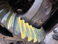
It's spalling.So your saying you wouldn’t run this cam?
The tappets are concave and they are offset off the centerline of the lobe. This makes the tappet rotate as the tip of the lobe goes vertical under the tappet. The trade off is that it overloads the oil film at the shoulder of the lobe and causes them to spall out. That cam is on its way out. Mine was identical when I tore down the short block I bought.
You can reuse it as long as you are ok with what it is going to do and the labor involved to replace it. It does have a little life left in it.
Sent from my motorola one 5G using Tapatalk
Nightmare90gt
New member

Nightmare90gt
New member
It's spalling.
The tappets are concave and they are offset off the centerline of the lobe. This makes the tappet rotate as the tip of the lobe goes vertical under the tappet. The trade off is that it overloads the oil film at the shoulder of the lobe and causes them to spall out. That cam is on its way out. Mine was identical when I tore down the short block I bought.
You can reuse it as long as you are ok with what it is going to do and the labor involved to replace it. It does have a little life left in it.
Sent from my motorola one 5G using Tapatalk
I will be replacing it looking at the Hamilton 178/208 with 103 springs and tappets.
Nightmare90gt
New member
Got the cam replace and degreed in. Been assembling the engine along with working on the front axle goal is to have the engine in by August but who knows what life holds.

Nightmare90gt
New member
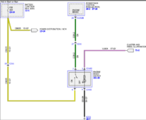
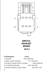
Has anyone been able to figure out how to get the exhaust brake to work? I am trying to use the ford switch and some of the wiring seems simple but here is what I have figured out. I can't figure out pins 2 and 6
Ford switch
Pin 2= Exhaust Brake Switch Signal or S/C Switch Return
Pin 3= illumination wire probably taken from the radio
Pin 4= Gound
Pin 6= Exhaust Brake Switch Signal or S/C Switch Return
The Exhaust Brake Lamp signal would probably need an LED light to show the exhaust brake is on but could probably be left out.
Attachments
Nightmare90gt
New member
I have Alldata for the dodge any suggestion on what to look up because most of the stuff is connector views not a wiring diagram. My understanding is you have to wire in the brake switch from the cummins ecm to make it work. I am going off of billet performance's 6.4 Powerstroke to 6.7 wiring he mentions it but doesn't go into too much detail.Need more info about the dodge side, but I am thinking it will be disabled without an abs input. You could get lucky. You need to know if the input to the Cummins ecm is 12 or 5v
Last edited:
Nightmare90gt
New member
According to Destroked it can't be done without the BCM. I am looking into a controller by BD diesel that the 5.9 can use that uses the vgt turbo to control it. I dunno if it will pan out or not but we will see.
CrimsonComet
New member
Ford dealerships or automotive electricians are like the superheroes of the car world when it comes to decoding these things. And yeah, those wiring diagrams... they're like trying to decipher a secret code sometimes.For the Exhaust Brake Lamp signal, you're right, an LED light would be handy to show when the exhaust brake is engaged. It's a nice-to-have for sure. It might be worth reaching out to a Ford dealership or an automotive electrician for some extra guidance if you're hitting a roadblock. Sometimes, those wiring diagrams can be a bit cryptic!
biggy238
Active member
What nonsense.Ford dealerships or automotive electricians are like the superheroes of the car world when it comes to decoding these things. And yeah, those wiring diagrams... they're like trying to decipher a secret code sometimes.
Nightmare90gt
New member
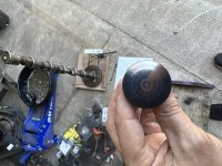
Can someone help me with this relay? It's called the Smart-Power relay but really can't tell which relay pin corresponds to the 1-5 on the diagram. This is how I think it's supposed to go but a little unsure.
pin 85-smart power relay return
pin 86-12v ignition
pin 30-constant 12v
pin 87-smart power relay feed
pin 85-smart power relay return
pin 86-12v ignition
pin 30-constant 12v
pin 87-smart power relay feed
Attachments
biggy238
Active member
Look at the gauge of the wires running into and out of the socket.
It should be pin 2 and 5 are the control circuit and 1 and 4 are the current handling circuit. The connector should have corresponding 16 gauge wires for the control and 12 or 10 gauge for the load/current handling. Also, usually the load terminal on that style relay it turned 90 degrees out of phase from its counterpart across the relay from it. 85 and 86 would be parallel to each other and 30 or 87 would be turned 90 degrees rather than parallel
It should be pin 2 and 5 are the control circuit and 1 and 4 are the current handling circuit. The connector should have corresponding 16 gauge wires for the control and 12 or 10 gauge for the load/current handling. Also, usually the load terminal on that style relay it turned 90 degrees out of phase from its counterpart across the relay from it. 85 and 86 would be parallel to each other and 30 or 87 would be turned 90 degrees rather than parallel
Nightmare90gt
New member
Hit another snag. It turns out the Destroked engine mounts don't allow for a driver-side starter so have to go with Diesel Conversion Specialist mounts to use the Dodge adapter with the Howards Allison SAE3 bell housing adapter. Not really what I wanted but have to adjust, my only grip with them is they are poly which causes more NVH than rubber.
Nightmare90gt
New member
That’s why I have to switch from destroked to DCS mounts is for the room.Interesting. My DCS mounts have a ton of room around the starter, but I'm running the Chrysler trans adapter