joestewart
New member
This is the 47RE out of my 1996 Dodge 2500. Bone stock. I burned up the clutches when I was towing. This is my second 47RE rebuild.
I disassembled this transmission and replaced all the clutches and steels. I have the main case assembled and ready to mate up to the overdrive.
I assembled the overdrive using the ATSG manual. I compressed the spring and installed the wire type snap ring and the waved snap ring.
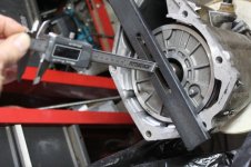
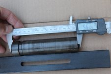
Then I went to take a measurement for the proper selective intermediate shaft spacer. I placed the overdrive in a holder such that all the components were moved rearward and the output shaft was not loaded. I used tool 6312 and 6311 just like the illustration in ATSG (see photo).
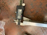
The measurement I get is 0.694 inches. See chart in the attached photo
0.694 inches is LESS THAN ANY OF THE RANGES GIVEN IN THE ATSG MANUAL.
So now I'm trying to figure out what could be wrong.
So the next thing I did is that I took another overdrive unit I had lying around and rebuilt it in the same way with new clutches and steels. When I took the measurement, I got essentially the same number.
Question: What could be wrong here?
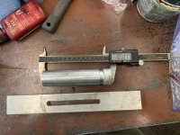
I measured the bar that I am using for the measurement and it is exactly 0.5 inches thick, which is correct.
I am thinking that this measurement is dependent upon several factors, but is independent of clutch stack thickness. It would seem like wear in any of the various components would result in an INCREASED MEASUREMENT (not a decreased measurement like the one I am getting).
I stopped by the local transmission rebuilder and ran it by one of the head honchos there and he thought about it for a few minutes and then suggested that I bring it in for him to examine. I kind of want to do this rebuild on my own so I thought I would run it by you guys first.
Does anyone have any ideas what could be causing my measurement to fall out of the ranges given in the ASTG manual on page 134?
Thanks
I disassembled this transmission and replaced all the clutches and steels. I have the main case assembled and ready to mate up to the overdrive.
I assembled the overdrive using the ATSG manual. I compressed the spring and installed the wire type snap ring and the waved snap ring.
Then I went to take a measurement for the proper selective intermediate shaft spacer. I placed the overdrive in a holder such that all the components were moved rearward and the output shaft was not loaded. I used tool 6312 and 6311 just like the illustration in ATSG (see photo).
The measurement I get is 0.694 inches. See chart in the attached photo
0.694 inches is LESS THAN ANY OF THE RANGES GIVEN IN THE ATSG MANUAL.
So now I'm trying to figure out what could be wrong.
So the next thing I did is that I took another overdrive unit I had lying around and rebuilt it in the same way with new clutches and steels. When I took the measurement, I got essentially the same number.
Question: What could be wrong here?
I measured the bar that I am using for the measurement and it is exactly 0.5 inches thick, which is correct.
I am thinking that this measurement is dependent upon several factors, but is independent of clutch stack thickness. It would seem like wear in any of the various components would result in an INCREASED MEASUREMENT (not a decreased measurement like the one I am getting).
I stopped by the local transmission rebuilder and ran it by one of the head honchos there and he thought about it for a few minutes and then suggested that I bring it in for him to examine. I kind of want to do this rebuild on my own so I thought I would run it by you guys first.
Does anyone have any ideas what could be causing my measurement to fall out of the ranges given in the ASTG manual on page 134?
Thanks