Intake manifold design

BramanteCummins

ADD maniac
Joined
Nov 1, 2012
Messages
636
This is a just a rough design. Ideas inputs and concerns welcome. Thought id share another one my projects.
 

Attachments

  • INTAKE MANIFOLD 2.jpg
    INTAKE MANIFOLD 2.jpg
    13 KB · Views: 0
  • INTAKE 1.jpg
    INTAKE 1.jpg
    19.6 KB · Views: 0
Looks really cool but have a few concerns
A wit all the angles looks really hard to fabricate
B the bolt goes threw the runner on back cylinder
C I think it will need more than 13 bolts to secure to head at high psi mine will have 22 and I am still concerned
D the intake opening circumference is not the same on all cylinder
My suggestion after building mine is take others work and improve don't try an reinvent the wheel. Good luck post lots of pics
 
Fabricating it wouldn't be too hard with the proper tools, once you get the design set.
Some jigs and templates, a few refinements and you could simplify it.
The most time consuming part would be the through holes/sleeves for the bolts.
 
The bolts are 5/16"-18 and the flange is half inch thick. I'm not too concerned about it sealing up. Should I? What do you feel the failing point would be?

The sleeves and thru holes isn't going to be too bad, just find the location and sink an endmill down on the mill.

As far as the ports not lining up or being the same size, I plan on cutting them undersized then working them to match the head a bit. Then I'll measure them and incorporate them into the model and program.

Reinventing the wheel is how innovations and advancements happen! I could copy someone else's design and call it a day but its still someone else's design. I need to be able to put my logo on it.
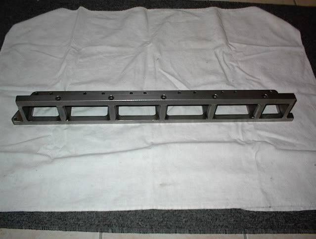
 
Make it out of as few pieces as possible, less chance of a leak or failure. Im assuming you'll tig it together?
 
I'm debating wether to get a pipe and cut it down the middle or roll a piece. Unfortunately I don't have anything to fold a sheet like that.

And yes, I don't remember the amperage on it but we had to downsize the torch when we first got it. Thing was way too big to work with
 
Like this bottem
DSC00005d.jpg
 
My concern is not in the bolts failing or flange flex rather in the threads that are tapped into head pulling. There is only so many places you can tap into head without hitting a water jacket or oil valley, And at best you really can only get about a quarter inch of tap in the good spots. ( at list that's all the farther I was willing to drill. ) ?
 
I think it's can be pretty tight for a bolt to go above the intake port. I was super careful and did a lot of research into both placement and still managed to hit a few water jackets with mine
 
Going into water doesn't matter. Use a good thread sealant and it is fine. I use ARP's thread sealer with 100% success.

I used 18 studs in head and 2 in a bracket in front of #1. It only leaked boost where the flange had 1/4" of seal behind #6.
 
That's my plan for #1 as well, a basic strap to the front. How did you only end up with a 1/4" of meat by #6? There's plenty of material there.
 
I ended up with 1/4" because of a poor design choice. That's really the only thing I would change on mine.
 
Back
Top