Tuning Twins

:Hey Gents
New guy here. I've been following this thread for awhile from the sidelines. It is definately one of the better threads out there for us getting introduced, & understanding tuning compounds. Thanx for all the info you all are posting!!!!. Have learned muchos.
I fiqured it was time to throw a couple words in for myself on this last post from Extended Power as I see it.
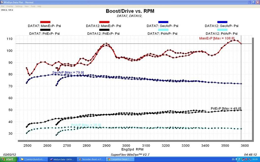
Having too large of an area, specially in the hot pipe can be a bad thing also, because you will loose velocity of the exhaust gases to the primary turbine, cause there will be less available pressure. The smaller the pipe/ housing is the more resistance or
pressure there will be, but you will have alot more velocity with the cost of higher temps.

liteweight
 
Last edited:
Instead of starting a new thread...since this pertains to tuning twins, I will put it here.

Basically a free flowing exhaust system..I mean right from the head/ heads, through the turbo, through the hot pipe, through the primary, and out where ever you have it plumbed, is what we are trying to do, right?

Less restrictions equals more power?

Need help with this:

Waste gate closed...you start to accelerate and the drive pressure starts to build as the secondary starts to spool up.
So right here, we have exhaust pressure coming into the turbo, transferring heat energy to the turbine blades, and spinning up the turbo...then exiting the secondary, on it's way to he primary. There is a pressure differential from the inlet of the turbine to the outlet...now my guess is, the more differential, the faster the turbo is going to spool up...(more heat, more energy, more power)
My reason for this is, if you where to block off the outlet of the turbine, you would be creating a restriction, which slows down the ability for the exhaust to flow through he turbine of the turbo.
Now, looking at the hot pipe...the exhaust pressure feeding the primary is in a way, the same thing...a restriction.
One thing I proved to myself, I have a QSV that I swap in and out for the primary turbo, and what I found was that with it in, it just created more back pressure on the exhaust system as a whole. Pressures and temps were up all the time. And when I pulled it out, the restriction was gone, and my drive to boost numbers came back closer to a 1:1 ratio for the primary.
Now, with the QSV in place, it was basically choking the whole system down, until everything opened up...but the temperatures say its not worth the little bit faster spool up of the primary. (in a single turbo app, these would be great.)
Now...back to the secondary.
If you have 100 psi going to the secondary, and 50psi coming out of it, you have 100psi on one side of the gates, and 50+ whatever the spring actuator is set at.
Now think about what is happening when the gates open on the secondary...if the primary is too restrictive,(too small of housing, and turbine wheel) it is a restriction, and just choking the secondary....isn't it?

My questions are: am I understanding this correctly?
To prove a point one way or the other, what would happen if you were able to get say 90 psi through the secondary, gated or otherwise...would it stall the turbo? (very small differential across the turbine wheel.)

This is why you would need to wastgate the primary.
 
Ok, but don't we want to drive the primary hard enough to get 30-40 psi out of it?

If I can't get 30-40 psi out of the primary, why would I gate around it?

Or are you going with my "if you had 100 psi on one side, and 90 on the other?" comment?
 
Last edited:
I have a 50mm gate on my primary (Garrett GT42-02 with 1.15 A/R T4 housing).

Wastegate limits it to 30 psi very well!!!


BRAAAAAAAAAAAAAAAAAAApppp
 
one thing to remember about turbines...


it's not the change in pressure that gives you the power. it's the change in temperature!!!

A gate just bypasses exhaust flow...it does not reduce drive pressure.

(Mass flow of the exhaust) X (the change in enthalpy of the exhaust gas) X (Turbine efficiency) = Turbine power.

Enthalpy (energy) is the combination of Pressure and temperature of the gas. Pressure is the minor player, temperature is the major player

Trying not to be a smart ass here, but how does a gate NOT reduce drive pressure?
Pretty sure if you put a 40mm gate on each manifold of a v8, the drive pressure will be reduced, wouldn't it?
 
Trying not to be a smart ass here, but how does a gate NOT reduce drive pressure?
Pretty sure if you put a 40mm gate on each manifold of a v8, the drive pressure will be reduced, wouldn't it?

That doesn't make any sense to me either, a wastegate is basically a pressure relief valve.

Sent from my DROID X2 using Xparent Blue Tapatalk 2
 
The boost pressure required from the turbo and the Engine RPM determine the power requirements for the turbine.


Two cases to analyze

Case 1, Using a Pressure relief valve to regulate Turbine Inlet Pressure (the "Flow Area" of the Turbine and wastgate varies only with Drive Pressure and is not referenced to the actual Power Requirement of the turbo):


Constant Turbine Inlet Pressure and Constant EGT = Dropping Boost as engine RPM rises.

Constant Turbine Inlet Pressure with Rising EGT = Rising or Constant boost pressure as Engine RPM increases


Case 2,

Using a Boost Pressure Regulated Waste Gate to regulate Boost Pressure: (the flow area of the Turbine and wastgate partially varries with drive pressure and is referenced to the actual Power Requirements of the turbo.

Constant Boost with rising RPM = Rising Drive Pressure

Constant Boost with Rising EGT = Constant or lowering Turbine Inlet Pressure

Constant Boost with Rising Engine RPM and Rising EGT = Constant or lowering Turbine Inlet Pressure (TIP could even rise in this case if EGT did not rise enough).
 
Last edited:
Like Liteweight I have learned a lot from this thread and I appreciate it very much. I was wondering if someone would be able to send me rlawless' spreadsheet.....I would appreciate it very much. Gonna start gathering parts here shortly for my compound setup...

aschbrk0528 "AT" hotmail dot com
 
If you pm him your email address he will send you a copy

Sent from my DROID RAZR using Xparent Blue Tapatalk 2
 
Well, I won't need this thread till my truck rolls again. I reached the peak of my factory headbolts retorqued to 125ft.lbs. just do you guys know, it took 75psi boost to blow it!
 
Well, I won't need this thread till my truck rolls again. I reached the peak of my factory headbolts retorqued to 125ft.lbs. just do you guys know, it took 75psi boost to blow it!

Wow....I thought they usually let go with anything over 45 psi?


Back on topic...sorta...

So what we are trying to do is balance out the work between the chargers....:badidea:

But...with the numbers I had posted earlier, I had 49% load on one charger, and 51% load on the other...pretty close to 50% work load on each if you ask me...problem was, even with the chargers sharing the work load equally, the overall drive pressure to boost pressure was nowhere near what a proper set up should be at. (1:1 ratio, or better...)

I have made more changes to my setup, and finally feel I am heading in the right direction.

Just accelerating, to get up to highway speed, I am now able to hold 30 psi drive to the secondary, and have 10 psi of boost out of the primary, and 30 psi overall boost going into the engine.:woohoo:

The math, if I'm doing it correct, looks like 3.04 overall pressure ratio, 1.68 on the primary, and 1.81 on the secondary.

More testing, and changes coming, as I want this setup to be perfect...


Jesus you will never get 1:1 across the whole power band especially if you are pushing the chargers to their potential.

Boost_drivevsRPM.jpg


I'll see ~1:1 up to 2500 or so and from then on up the spread widens.

Just look at the boost/drive of the primary...that's with the 96 turbine and 1.32 housing.

Frankly from my data and results to optimize the system more I'd throw a even bigger housing the the primary.
 
I don't expect it to be a perfect 1:1 the entire rpm range...but if I can get it to hold closer to 1:1 longer throughout the rpm range, and be able to spool up the primary faster without the loss of boost pressure, I think thats better.

I'm making small changes to my setup, and passing them on...

On your graph there...Am I reading this correct:

Your average exhaust pressure to your secondary is about 95 psi.
Average output from the primary is 35-36 psi. (Very consistant)
Average overall boost to your engine is about 75 psi.

I'm not sure what the other "Primary Exhaust" pressure is...is that the drive to your primary from the secondary? (Average is about 45 psi??)
 
I applaud the sharing of the results, helps others from your work.

Don't look at the "average" look at the data. At 3500 that s480 with the 96 turbine/1.32 housing is already at 1.5:1. Your primary with an even smaller housing and marginally less powerful turbine is bound to be worse yet....

The data also shows a s480 will do 35lbs boost at 2500 rpm....IMO there is absolutely no reason for a smaller primary.

There's a vid of one of Pius's triple setup's on here, and if you watch the guages you can watch the boost come up considerably before the primary needle even lifts, yet seamlessly starts to contribute when right when the secondary needs it.

My guess is your boost gauges are coming up in tandem, primary boosting very early and actually contributing to total system lag.

IMO your looking for a smaller compressor on the secondary and a larger turbine and housing on the primary.
 
Extended Power, have you thought about trying a larger turbine housing on the secondary with a smaller wheel? Less velocity at lower rpms but the turbine wheel wont require as much to reach is map, and then less restriction from the secondary at higher RPMs and more DP to the primary? Just thinking out loud?
 
Back
Top