Turbo sizing, deeper discussion

Now how does a turbine wheel determine available shaft HP to drive the compressor?

There are many variables of the blade design, blade count/trim, and of course weight. Typically in a single pressure stage when the compressor inducer is too close in size to the turbine exducer, surge is common in lower engine speeds. However in a multiple pressure stage setup this is not an issue, and it makes sense to run these values closer together to maximize the potential of both turbochargers.

The following is a good example of two very different designs, of similar size, that will create similar power. What the G-trim turbine(11-blade) on left lacks in blade surface area, it makes up for in weight when compared to the GT60 turbine(10-blade) on right.

steverodneytony008-vi.jpg
 
Last edited:
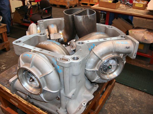
The 73/80mm S300 turbine wheel on left is machine clipped from the manufacturer, it is clearly a different blade profile than the 68/76mm S300 turbine wheel on right.

321599_261013630604872_1625442018_n.jpg

So. This might be a terrible assumption but I will ask anyways.

Nearly every turbo we see at work on all of the larger engines C12, C10, ISM, M11, etc.. have the curved blades on the turbine side and appear to look identical in basic design to the turbine on the left hand side. These turbos generally are quite small in size for their application I had always thought. The largest (compressor inducer size) I see is a K31 (71mm) on a detroit 60 series. The rest tend to be 67mm or smaller. I had always found that odd. Is it fair to assume, for lack of a better way of describing it, the "curved" blade design flows more on the turbine side? Is this how in the heck they are able to put such turbos on big truck engines? Or is the flow needed on the exhaust side accomplished with the massive t6 1.3ar or larger exhaust housings so I am way off base?
 
Last edited:
I had always found that odd. Is it fair to assume, for lack of a better way of describing it, the "curved" blade design flows more on the turbine side?

It is common to see a greater "spread" between the compressor wheel size and turbine wheel size on large diesel engines. Generally speaking the compressor is kept to a minimum size to decrease lag for emission reasons, however the turbine must be kept to a certain size being each cylinder displaces a great amount of exhaust gas per stroke. I am going to post one of the best explanations of this concept I have seen, as I feel it fits into this topic well;

dizuster said:
So lets make an easy example (with fictitious easy to understand numbers) to show why peak pulsing pressures are not all the same. Engine one is twice as big as engine number two… but runs at half the RPM.

Engine #1 - 10 pulses of 1lb each in 1 second… 10pulses x 1lb / 1 second = 10lbs/sec.

Engine #2 - 20 pulses of 0.5lb each in 1 second… 20 pulses x 0.5lbs / 1 second = 10lbs/sec.

So both of them flow 10lbs/sec… but what’s actually happening inside the engine is much different.
If you looked at the pulses… they would look something like this (not exactly… but you get the idea).
Graph1_zps9d397ecf.jpg


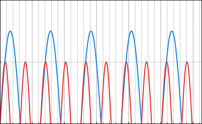
Few big tall pulses for the big/low RPM engine… and many small short pulses for the small/high RPM engine.
But as was said before (and depicted in the flow charts previously in this post), there is a mass flow “choke point” to every turbine housing/wheel combination. What happens when that big pulse of the V8 “chokes” the turbine?... Then the flow will actually look like this…
Graph2_zps352c5e47.jpg


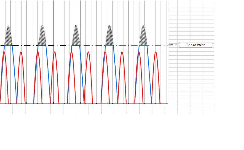
Anything above the choke point (shown in grey hatching) will not actually flow as hoped… which means the pressure will continue to go up in the cylinder, but the flow will not increase.

What does this mean for the turbine? As outlined above, the flow through the turbine is maxed for a given pressure/flow once choked. The V8/Large Engine tries to force feed the turbo a huge volume of air on each exhaust stroke. This huge volume of air gets choked off, and does NOT flow through the turbine. This is what’s actually happening when you max out the hot side of a turbo.

This is also exactly why a small motor (with high RPM and many small exhaust pulses) can get more out of a given turbine then a big motor (with low RPM and few large exhaust pulses).

Both have the same overall flow rate, but they do it in different ways.
If you have a small motor, it will “pulse” many times (High RPM) and at lower air mass flow (small motor) for each exhaust stroke. These small pulses never go over the “choke point”, so they never lose any overall flow. The large V8 motor will do the opposite… it will pulse fewer times (low RPM) and at a higher mass flow (large motor) for each exhaust stroke. Each time the large engine pulse goes over the choke point, the piston is pushing harder (robbing horsepower), but getting no additional flow for the work it’s doing.
Since you can only shove in, what you can shove out… the small motor at high RPM can use more compressor for a given turbine/exhaust housing then the large V8 motor can.
 
Last edited:
Thank you! This is a very informative thread! This helps explain how a tuner can get so much out of a given turbo compared to the diesels. Also helps explain how smaller gas tuner engines are able to run turbines that are closely matched and sometimes smaller than the compressor side without as many issues.
 
Yes it does!

I want to know turbine flow rates now. I bet if we can get that, turbo tuning as a whole can get more precise leading to cleaner and more complete burning of fuel.
 
This is why I am not a fan of using turbochargers from a large cubic inch diesel engine as a primary on a small cubic inch diesel engine and expecting it to be ideal for both applications.

From years of reading forums such as this, it is very clear that turbochargers in general are the largest area of misunderstanding and unrealistic comparisons.
 
Last edited:
Some instances are worse than others, for example a GT5002 - 75/102mm compressor and 91/99mm turbine and a 1.26AR housing, this would work well for it's intended application on a large cubic inch Caterpillar engine, but would be a poor candidate for a primary turbocharger on a smaller cubic inch diesel engine. However let's say the compressor size was increased to 88/118mm, it would then be quite potent in the power department on a smaller displacement engine.
 
So what you're saying is: Box stock turbos that are used for larger engines that we use for primaries do not have ideal turbine to compressor sizing.
 
Weston, this is why you design my turbos :D thanks for sharing your knowledgebase! Makes me think and gives me even more ideas!
 
I would think the large turbo in a traditional compound set would receive mostly linear flow. No?

This is what I would have assumed?

If most high pressure turbos are also being wastegated you would assume that it would be on the or above the choke point the higher peaks as in the diagram above are being "muted" to some degree before reaching the primary?

Thanks for the input, great info. :Cheer:
 
So what you're saying is: Box stock turbos that are used for larger engines that we use for primaries do not have ideal turbine to compressor sizing.

In my opinion no. Since surge is not an issue in a compound arrangement, I see it wise to maximize the potential of the compressor given the adjacent turbine size.

I would think the large turbo in a traditional compound set would receive mostly linear flow. No?

The exhaust gas entering the low pressure turbine will not be steady state, but if you are referring to it being more linear as in not seeing the engine pulses directly, then yes the high pressure turbine should subsequently dampen this.

If most high pressure turbos are also being wastegated you would assume that it would be on the or above the choke point the higher peaks as in the diagram above are being "muted" to some degree before reaching the primary?

I would also make this assumption, increasing the turbine AR is somewhat of a crutch to avoid choke flow, the only two real solutions are a wastegate bypassing the turbine or a larger turbine wheel itself, both of which are incorporated in most factory equipped compound setups.
 
It is not all together uncommon to see a large displacement engine use smaller automotive turbochargers in a two stage setup, this helps to widen the power band in comparison to a single stage setup. Paxman for example has used this concept on both 12 cylinder and 18 cylinder engines, intercooled between stages and aftercooled post high pressure stage.

box3ntop.jpg
 
Back
Top