ZEXEL pump , trick the TICS .

Orstraylian

New member
Joined
Jun 25, 2016
Messages
4
Hello all from OZ .
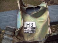
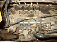
I am fitting an FD46TA Nissan Diesel to a tracked forestry mulcher I am building . It has a ZEXEL pump which is an electronic version of your P pump . I bought the engine complete with the wiring loom and ECU but I have had a large fail . I had the ECU sitting on the pallet with the engine and when I carried the pallet out of the shed with the tractor , the ECU must have fallen into the grass . We had a grass fire coming towards us a couple of days later so I quickly mowed around the shed to stop it from catching on fire . Look what I found after I mowed .
:doh:

Question is , did you guys ever work out how to run an electronic pump without an ECU ?
 

Attachments

  • Zexel 008.jpg
    Zexel 008.jpg
    62.1 KB · Views: 0
Is it not just a simple matter of attaching a rheostat to the throttle linkage on the pump and sending the variable voltage to the TICS unit to control the fuel ratio and advance ?

It takes around 5 volts to swing the arm in the TICS that controls the fuel enrichment rail and rack . I cannot see why you couldn't use a rheostat with an appropriately scaled linkage attached to the pumps throttle linkage by way of a link rod and rose joints to deliver the correct voltage to the TICS unit .

If idle was NO voltage coming out of the rheostat and full throttle was 5 volts coming out of the rheostat and into the TICS , every other throttle position should be pretty close to what the pump should be doing to keep up with the demand on the engine .

It obviously wouldn't be as refined as having the inputs from a bunch of sensors like water temp, air flow etc but shouldn't be far off .

I am thinking I could use a Rheostat or a Hall Effect linkage unit and then into a controller that would deliver the voltage needed for the TICS .

Any ideas ?

If this worked , ZEXEL 4 cylinder truck pumps like mine on 4BT's and 6 cylinder pumps on 6 BT 12 valves would be easy .
 

Attachments

  • Zexel 001.jpg
    Zexel 001.jpg
    76.6 KB · Views: 0
  • he.jpg
    he.jpg
    4 KB · Views: 0
  • pot.jpg
    pot.jpg
    37.6 KB · Views: 0
Just a quick doodle to give you a visual of what I have in mind .
 

Attachments

  • rheostat.jpg
    rheostat.jpg
    77.9 KB · Views: 0
Welcome! I have zero idea what a TICS is, but couldn't you just use a mechanical linkage to swing the arm in the TICS? If not, do you have any idea of the amperage involved for the 5v signal to move the TICS?
 
Welcome! I have zero idea what a TICS is, but couldn't you just use a mechanical linkage to swing the arm in the TICS? If not, do you have any idea of the amperage involved for the 5v signal to move the TICS?

Hello and thank you for your welcome and your question .

TICS stands for Timing & Injection Control Systems . It is an electronic means to controlling fuel input and advance .

I dont if someone could manufacture a housing and linkage to manualise it . I wold like to keep it electronic and just supply controlled power to it , if at all possible . I have resistance values for every component for testing but power demand values to operate it . Getting information on the Masons is easier . I am hoping some switched on pump guy here may be able to help with the Tech .

https://www.youtube.com/watch?v=U9VNiUu1XUM
 

Attachments

  • TICS.jpg
    TICS.jpg
    64 KB · Views: 0
Last edited:
It's not a CAN or other bus-type system, it's straight up 0-5vdc control?
 
Tics pump are very complex to build and calibrate. I could have lived the rest of my life without hearing about them.
 
Back
Top