Cummin-a-long
Big Angry
- Joined
- Jul 24, 2008
- Messages
- 787
This is just the break-off and continuation of the Brian beat down....
From the other thread....
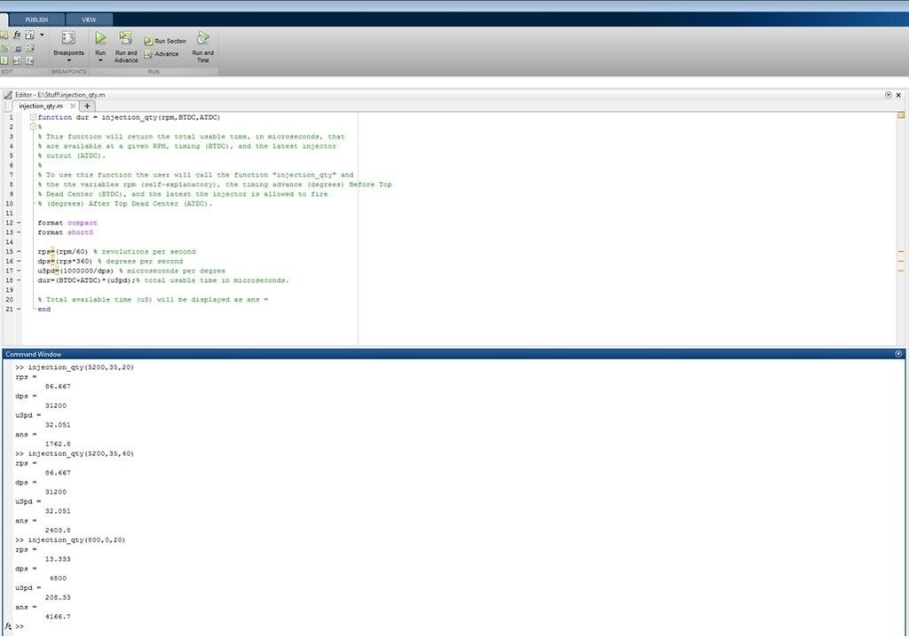
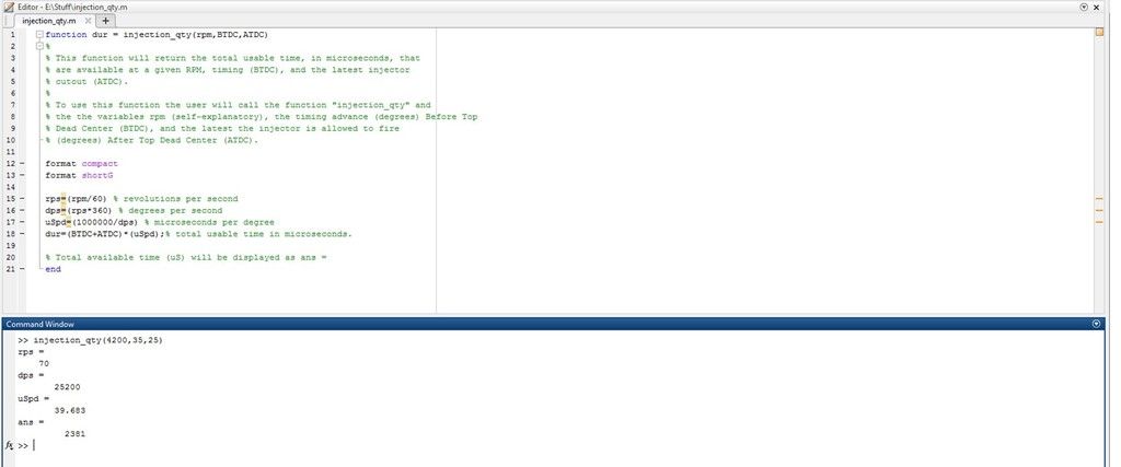
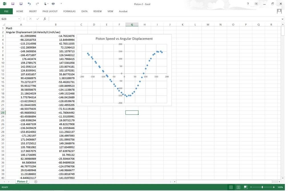
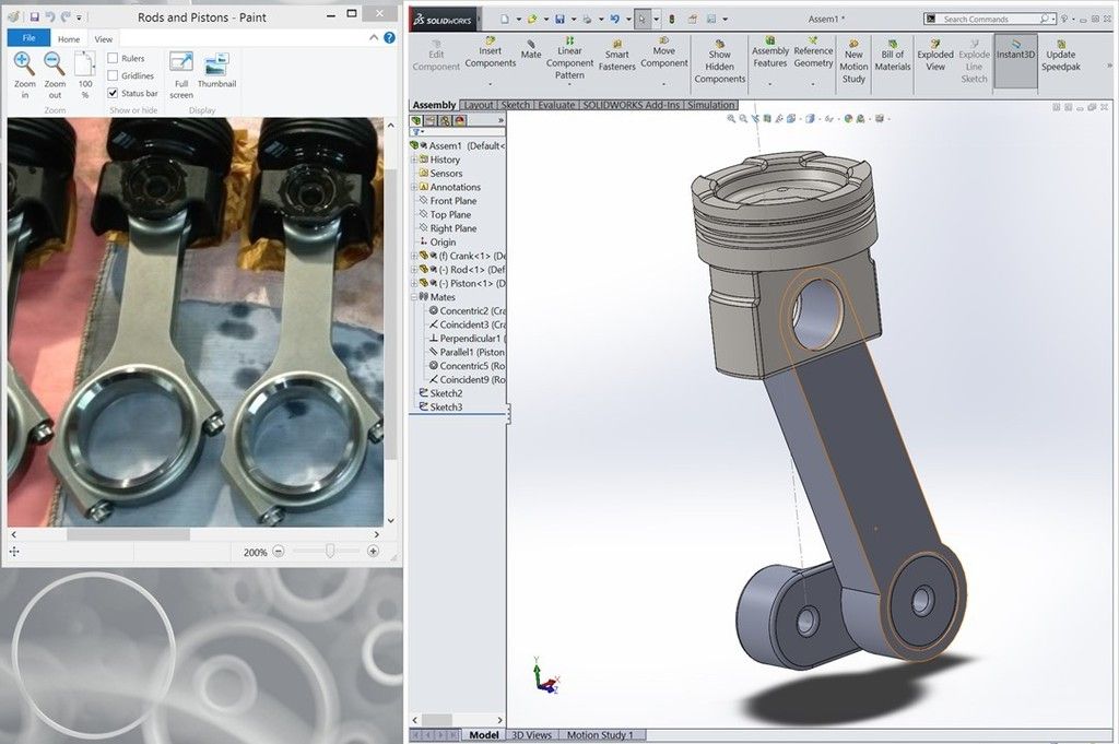
For those that have never actually calculated some of this stuff, here is just a small example of how it gets done.
This is just a VERY simple calculation that gives you the TOTAL amount of time that you have at a given RPM, with a given amount of timing BTDC, and whatever you set as your latest injector cutout ATDC.
This IS NOT the actual fuel quantity you'll need, this is just giving you the actual time you have available and can help you spec your injectors so you actually get full power at the RPM's you want to turn.
Here is an example of my truck at 5200 RPM's with 35*'s of advance and a max of 20* ATDC before injector cutout.
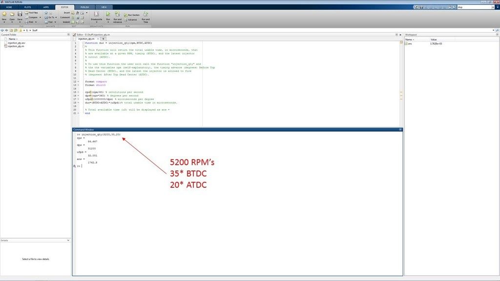
Now, in order for me to stretch my fuel system out and drop pressure, based on what I know my pumps can flow, I'd need to be exceeding 2400 uS up in those RPM's and in order to do that I'd need to be injecting WAY beyond that 20* ATDC...40*, which is pretty useless at those piston speeds, is actually where this would occur. This would be a hot, smokey mess.

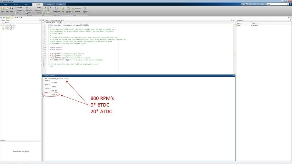
Now, just to show that this function DOES NOT tell you what your fuel quantity ACTUALLY needs to be, here is the total time you'd have at idle (800 RPM's) with 0*'s of advance and 20* of max timing ATDC. You'll see the available time is HUGE and is why you see some of the really ridiculous values that are in the OEM fuel mapping.
This would look like an old coal fired train idling in your driveway if you used this value.
I have others that I made for timing, ACTUAL duration, injection velocity, cylinder pressures, etc., but those I keep pretty close hold.
But, you get the point here...this stuff is not hard to calculate if you know what to look at.
From the other thread....
For those that have never actually calculated some of this stuff, here is just a small example of how it gets done.
This is just a VERY simple calculation that gives you the TOTAL amount of time that you have at a given RPM, with a given amount of timing BTDC, and whatever you set as your latest injector cutout ATDC.
This IS NOT the actual fuel quantity you'll need, this is just giving you the actual time you have available and can help you spec your injectors so you actually get full power at the RPM's you want to turn.
Here is an example of my truck at 5200 RPM's with 35*'s of advance and a max of 20* ATDC before injector cutout.
Now, in order for me to stretch my fuel system out and drop pressure, based on what I know my pumps can flow, I'd need to be exceeding 2400 uS up in those RPM's and in order to do that I'd need to be injecting WAY beyond that 20* ATDC...40*, which is pretty useless at those piston speeds, is actually where this would occur. This would be a hot, smokey mess.
Now, just to show that this function DOES NOT tell you what your fuel quantity ACTUALLY needs to be, here is the total time you'd have at idle (800 RPM's) with 0*'s of advance and 20* of max timing ATDC. You'll see the available time is HUGE and is why you see some of the really ridiculous values that are in the OEM fuel mapping.
This would look like an old coal fired train idling in your driveway if you used this value.
I have others that I made for timing, ACTUAL duration, injection velocity, cylinder pressures, etc., but those I keep pretty close hold.
But, you get the point here...this stuff is not hard to calculate if you know what to look at.