Ahhh but why do you say NA is so much different?
The reason equal length primaries are used is two fold:
Scavenging: This is what happens on a properly designed manifold in the collector. As the pulses arrive at the collector, and given the cylinder pairing was done correctly the pulses will arrive at EVEN INTERVALS, so as one pulse from one primary enters the collector it creates a vacuum in the direct neighboring primary and helps suck the pulse into the collector, this helps reduce the EMP (exhaust manifold pressure). Reducing exhaust manifold pressure helps reduce the amount of spent exhaust gasses that get trapped into the cylinder which prevents more fresh (and hopefully cold!) air re entering the cylinder on the intake stroke.
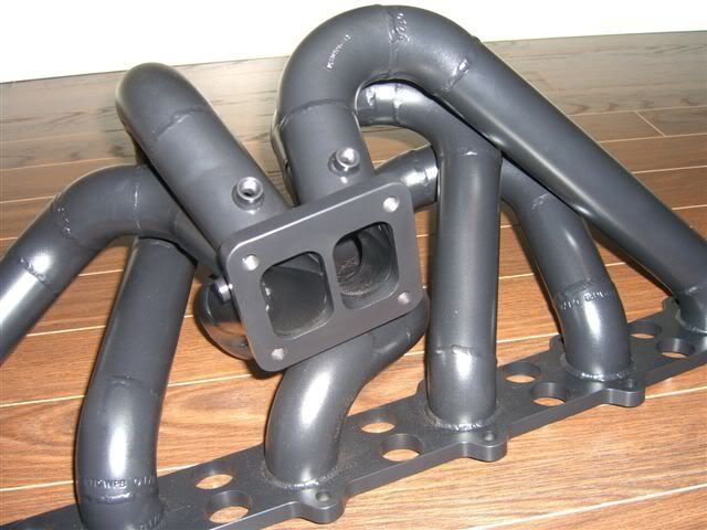
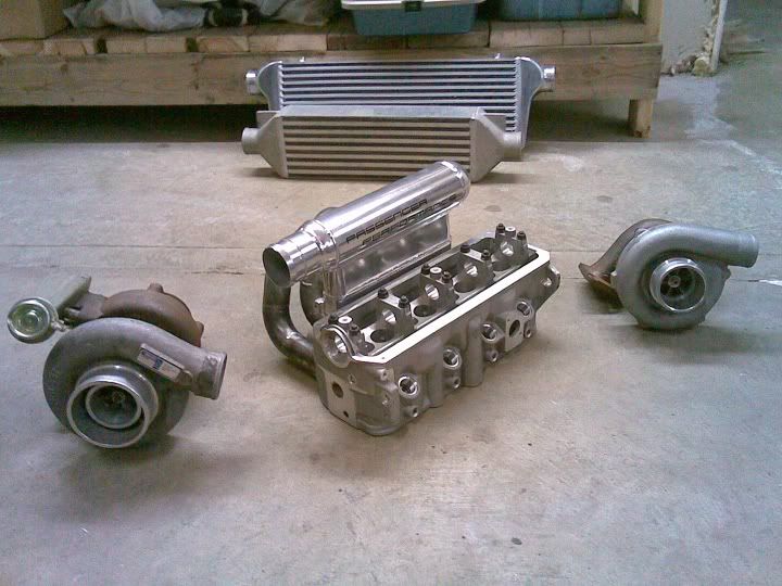
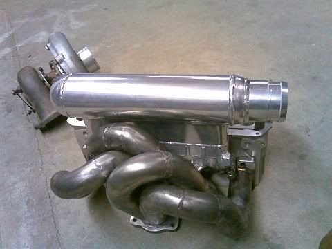
Pressure: Equal length primaries are also done to achieve a pressure balance on each individual primary, balancing the pressure on each primary also helps balance the egt for each primary, which helps balance the egt for each cylinder, and also helps balance the PEAK cylinder pressures across the cylinders. If there is more pressure on one primary than another the primary with more pressure keeps more spent exhaust inside that cylinder and creates the un desireable side affects mentioned above. The reason I used two EMP's (one for each side of the scroll) is in effort to monitor an imbalance between the cylinders. I can't of course expect them to be perfect yet as I still need to remove the head, remove the stock integrated cast "intake manifold" and build a real high quality lehman style intake manifold.
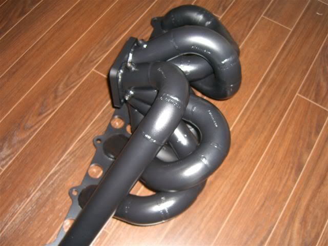
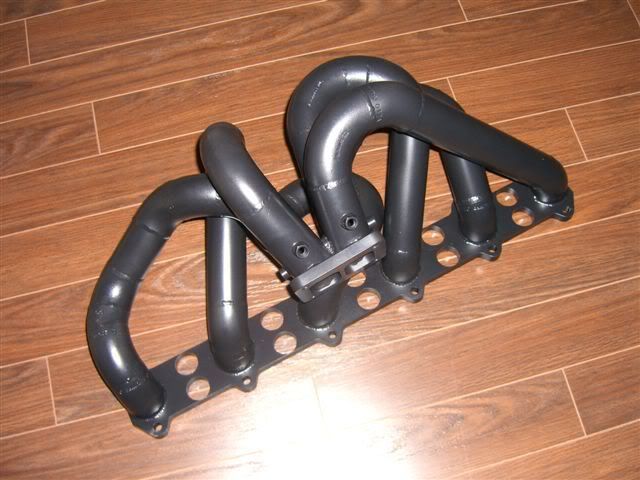
As for the comments on the welds its actually the coating that makes they look bad, its a ceramic coating that we applied too thick and it globbed funny on the ripples of my tig welds. I'll get some close up pictures of the welds for you guys to see, I am a tig welder by trade, high pressure pipe, SS sanitary welding etc.
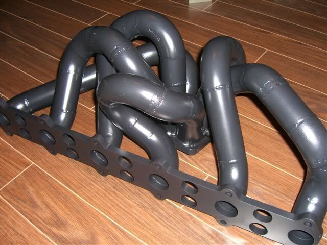
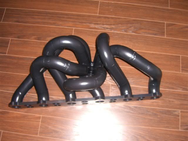
The fitting on this manifold are sch40 1.5" (thats 4mm thick, or .157"). All the welds are full penetration, this manifold weighs in at 37 lbs. The flanges are CNC milled from 1018CRS .5" thick.
As for time in this manifold, well the construction was the fastest part, the engineering takes the longest, and all the programming for the flanges to run on the cnc mill, designing the collector and playing with angles, it all takes a lot of time, theres a lot of machining on this thing, the collector is cnc milled, the flanges are cnc milled, the straight sections are cut and beveled on a cnc lathe, and the fitting and welding was done by yours truly. Probably a good 200 hours into the project so far.