You are using an out of date browser. It may not display this or other websites correctly.
You should upgrade or use an alternative browser.
You should upgrade or use an alternative browser.
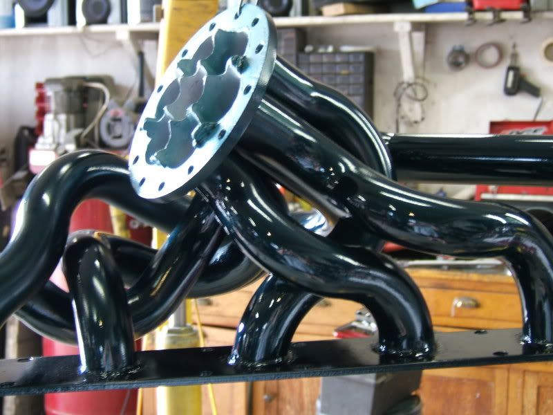
Someone had to do it, cummins tubular manifold.
- Thread starter PASSENGER
- Start date
oldschoolPSD
My Trucks are Obsolete
- Joined
- Jul 24, 2006
- Messages
- 891
Seems to me a tubular manifold would be nearly impervious to cracking. It might expand and contract and cause leaks, but I highly doubt it would crack like a cast manifold.
Holeshot
Diesel Sherpa
- Joined
- Apr 24, 2006
- Messages
- 74
Hey, Dave:
Is this manifold for a common-rail Cummins up on your website yet? :bang - Just giving you crap, man.")
This isn't the first tubular exhaust manifold made for a Cummins B-series, but it might be the first designed for a common-rail B-series.
I'll need something like this for my 4-cylinder Cummins "ISB 170" before long.op:
Matt
Is this manifold for a common-rail Cummins up on your website yet? :bang - Just giving you crap, man.
This isn't the first tubular exhaust manifold made for a Cummins B-series, but it might be the first designed for a common-rail B-series.
I'll need something like this for my 4-cylinder Cummins "ISB 170" before long.
op: Matt
Double J
New member
- Joined
- Oct 3, 2006
- Messages
- 1,251
mech2161 said:Now you need this intake to go with it.
:bow: Got more pics?
dzlfarmboy
Supporting Vendor
- Joined
- Jun 27, 2006
- Messages
- 2,448
mech2161 said:Now you need this intake to go with it.

I believe i saw that pic a long time ago on Advanced Diesel Technologys website
mech2161
I have a secret.
- Joined
- Jan 15, 2007
- Messages
- 3,986
Yep that's it! http://www.smokindiesel.com/ Look under customers rides page 3.
PRattenbury
Neophyte
- Joined
- Jan 28, 2007
- Messages
- 1,095
I like it! Did it make any improvement over a plenum, though?
oldestof11
Drag racer
- Joined
- Jul 17, 2007
- Messages
- 9,084
We who have 1st Gen have a TON more room over on that side of the bed. Even though I am not pushing that HP/TQ/EGT to need one, I will have to remember you. Great job! I will have to see if you modify one for 1st Genners.
PASSENGER
Bells and Whistles
- Joined
- Jun 8, 2007
- Messages
- 267
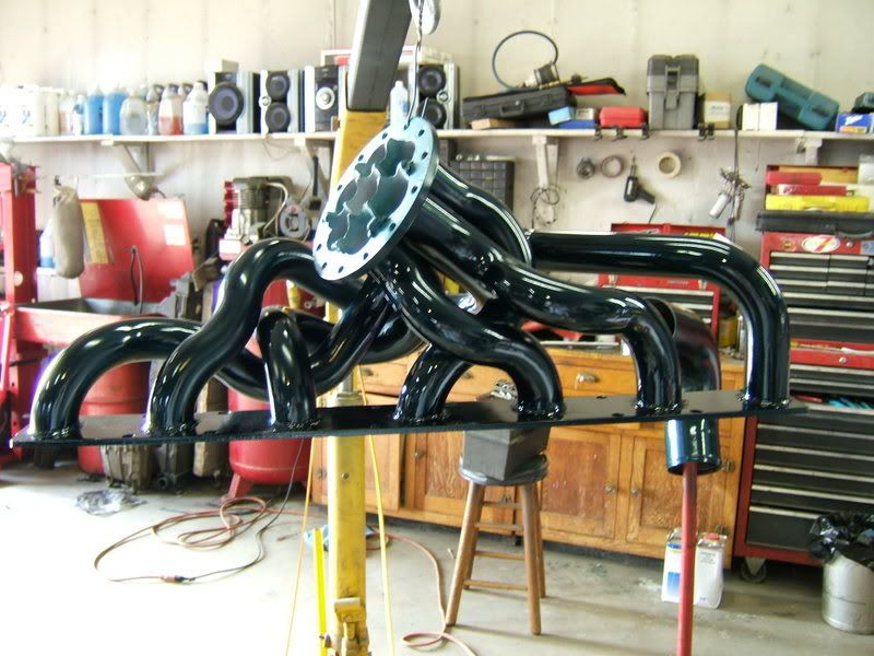
The primaries are measured by center line radius, so yes they are in fact equal length. ZZ fabs manifold is basically a copy of the stock one, which to me seems pretty funny, if you are going to that much trouble to port the intake ports why not build a proper intake manifold. I have a good intake manifold in the works but I doubt I will be done it before September. The VW tdi intake manifold I posted earlier is a design popularized by Audi known as a "Lehman" style intake manifold. It utilizes 2 plenums, with a narrow slot dividing the two to aid in creating equal pressure and flow across the ports. We are working on building a positive pressure flow bench to accurately measure the flow in both intake and exhaust manifolds under positive pressures with flow rates that are comparable to actual engine operation.
Yes several other manufactures manifolds are prone to cracking, mine are not, the difference is in material selection, weld quality, and engineering. I've never had a single manifold, downpipe, aftercooler tube, high pressure pipe, low pressure pipe, sanitary tube etc fail on me ever, and I've built hundreds, the key is in over engineering and going the extra mile than the industry standard.
As for the DI performance manifolds, those are typical of the automotive industry, based off it fits and looks, not the engineering. To me that is the single biggest pitfall in the automotive industry, lack of engineering, too much guessing, my daddy did it this way, I did it this way for 40 years... bla bla bla.
That green intake manifold reminds me of a Toyota intake manifold I think around a 2000 corolla manifold, same idea, except I believe the Toyota's has equal length primaries. While I respect and still play around with tuned intake manifold runner lengths the benefits of harmonic tuning I don't find to be as great as equalizing flow and pressure even across the ports, hence why I focus more on Lehman style manifolds, trying to distribute the air as evenly as possible across the ports under POSITIVE pressure.
If these manifolds work out well I will likely build some first and second gen versions...
gitchesum
New member
- Joined
- Apr 30, 2006
- Messages
- 1,140
I've been testing something similar, only in stainless.
It's nice to drop EGT's by almost 200 degrees with just a manifold.
This is a temp trend on a 04 CR with a stock turbo, running the Smarty Beta 4.3 and the TST on 4/4
It's nice to drop EGT's by almost 200 degrees with just a manifold.
This is a temp trend on a 04 CR with a stock turbo, running the Smarty Beta 4.3 and the TST on 4/4
Attachments


PASSENGER
Bells and Whistles
- Joined
- Jun 8, 2007
- Messages
- 267
gitchesum said:I've been testing something similar, only in stainless.
It's nice to drop EGT's by almost 200 degrees with just a manifold.
This is a temp trend on a 04 CR with a stock turbo, running the Smarty Beta 4.3 and the TST on 4/4
Whats the pressure and temperature differential between the front and rear cylinders?
I agree, drastically reducing EGTs is a major benefit!
gitchesum
New member
- Joined
- Apr 30, 2006
- Messages
- 1,140
I didn't have enough pressure sensors to run a front to rear pressure differential, but the #1 cylinder EGT is running considerably higher than #6, but lower than all 3 rear cylinder combined.
Turbo drive pressures are in the 75 psi range with the boost pressure running around 40 psi.
At WOT, the data logger was seeing almost a 80degree difference between #1 and #6, with #1 being higher.
Oddly enough, the rear 3 cylinder combined were running almost 200 degrees hotter than #1 alone.
Turbo drive pressures are in the 75 psi range with the boost pressure running around 40 psi.
At WOT, the data logger was seeing almost a 80degree difference between #1 and #6, with #1 being higher.
Oddly enough, the rear 3 cylinder combined were running almost 200 degrees hotter than #1 alone.
Attachments

Last edited:
Tuning this manifold for harmonics is really out of the question in this application because the tubes are going to be so short. I'd have to run the numbers, but I'm sure they would need to be in the 45+ inch range for the rpm range we run. The firing order of the I6 bodes well for an equal length header to deliver exhaust pulses in even intervals to the turbocharger. I would suggest thinking of a bracket to run between the mounting flange and the turbo flange to further support the charger. Oh, and a provision for an external wastegate would be a big plus! Looks nice!!
PASSENGER
Bells and Whistles
- Joined
- Jun 8, 2007
- Messages
- 267
What are you using for a datalogger? I am in need of something of the sort very soon.
Hmmm I would think that the reason the three rear cylinders run hotter would be due to such a small volume, causer higher pressure/resistance, causing more heat... What are your thoughts on the cause for this? Why #6 is so much lower than rear three combined and compared to #1 is very interesting, I'm gonna be thinking about that. Really makes you wonder what the temps of 4 and 5 are like. Really sucks that the stock "intake manifold" sucks so much, its really throwing a lot of hard to measure variables into measuring things on the exhaust side, can't wait to try and fix that.
Have you worked on building a better intake manifold at all?
Keep up the good work and research I'll be comparing my results to your hopefully quite soon!
PASSENGER
Bells and Whistles
- Joined
- Jun 8, 2007
- Messages
- 267
banshee said:Tuning this manifold for harmonics is really out of the question in this application because the tubes are going to be so short. I'd have to run the numbers, but I'm sure they would need to be in the 45+ inch range for the rpm range we run. The firing order of the I6 bodes well for an equal length header to deliver exhaust pulses in even intervals to the turbocharger. I would suggest thinking of a bracket to run between the mounting flange and the turbo flange to further support the charger. Oh, and a provision for an external wastegate would be a big plus! Looks nice!!
Again I agree on the harmonic tuning, the other thing is that harmonic tuning works for such a limited RPM range, equal pressure and flow benefits all rpm ranges!
I actually intentionally did not install a bracket between the head flange and the turbine inlet flange, reason being that I do in fact want the runners to be able to move if needed, interesting thing I noticed when using these steel sch40 fittings compared to SS sch40 fittings, the steel ones did not contract more than .005" end to end during welding! SS runners would have shrunk at least .085-.15". What this helps show me is that these primaries will likely not be expanding or contracting an excessive amount during operating temperatures, especially with the ceramic coating INSIDE and OUT.
All that said if in testing we realize a need for bracing I will do something about it! Likely a Heim joint bracing system to allow the runners to move, instead of a solid brace welded from flange to flange which would only add stress in the way that it cause stress risers where the runners want to move!
As for external waste gate, two would be the answer here, twin 38mm gates would be great, one for each scroll to keep the pressure differential even. I wanted to run twin external gates but the owner had already bought this turbo and is hell bent on at least trying, so try we will. I think externals are the way to go no doubt, if I produce these that will undoubtedly be an option.
Any other suggestions, comments etc I would appreciate them, I want to build the best manifolds I can. Thanks for the props guys!