Supercharger pulley

FYI, the CR damper is 8-3/4" on the OUTER ring and there is room to cut the diameter down, if need be.
I believe this is similar in dimension to the VE Cummins, yet it has the larger (7-7/8") diameter pulley track.

Mark.
 
Last edited:
Startings of the forward mount, a piece of 3" angle that follows the contour of the alt bracket. I'm going to punch out the other mounting hole and possibly box the backside of that end in so it pushes on that bracket a little more squarely.

0CCCB77F-6AD3-4390-9FC7-413642D21A94-1707-000001B06306CBC6_zps1484bfbf.jpg


Honestly, I may not change the rear mount too much. It's sitting there holding the weight of the entire setup right now and not sagging a bit. I may brace it up some so it doesn't flex out wards with the front brace as a pivot, but I think just making the front brace stouter towards the about end of the mount will be just as effective.
 
Coming from someone who's owned one of these things you know damn well I don't. The ride's so bad working on them is really the only thing that makes sense to do. :poke:


Welded, drilled, and waiting for my cousin to cruise up and tack it in while I hold it in place. I may redo that inner bolt to a bigger one but probably not. I'd have to drill out its boss on the block its entire length and that doesn't seem enticing.

DF5643E5-F804-454B-AC73-706CD2A0D502-1745-000001BB5F9D45CE_zpsf7b79603.jpg
 
Holy Long drive belt, Batman! :doh:
I see potential points to attach idler brackets and a tensioner for more "wrap".

Mark.
 
Last edited:
Heh, Caleb sent me a couple old belts with the non-IC'd AC stuff I bought and I found the perfect use for them. That one I've got all folded up is the factory AC belt which, believe it or not, will be the perfect size to use when I get that idler put in to make the flipped fan hub work. Kinda weird how that stuff works out, huh?

I've got the mount tacked on and I'm shaking the whole truck with it. Unfortunately, that rear mount definitely isn't going to cut it. It lets the rear wiggle around way too much. :doh:
 
This CR crank pulley intrigues me, the actual pulley diameter on it is 8", right?

Is the bolt pattern and offset the same as a 12v? Would the balancer aspect of it still work since the internals are different in little ways?

FYI, the CR damper is 8-3/4" on the OUTER ring and there is room to cut the diameter down, if need be.
I believe this is similar in dimension to the VE Cummins, yet it has the larger (7-7/8") diameter pulley track.

Mark.

Thanks Mark. I dont have a VE damper to compare to. Maybe ask fluidamper or ATI about specs?? I'm sure they could make a custom one as well if it came to it.
I think the larger crank pulley may be a contributor to CRs blowing freeze plugs so often...
 
Well, the CR damper won't work without some mods (as Levi suspected) to the pan and timing case.
The damper won't sit square to the crank by ~3/16", becase it's hitting the timing case near the 2 center bolts.
Here's some REALLY crappy pics to illustrate where it will contact;

Bottom side:
CRVEdamper2_zps76f135e6.jpg


Driver's side:
CRVEdamper0_zps8bf17e36.jpg


Passenger's side:
CRVEdamper1_zpsd0cbd04c.jpg
 
Mark, the CR uses a tone ring. did you try it with one?
maybe cut the tone ring to be used as a spacer?

how is the alignment to the other pulleys?
 
Last edited:
Carl, no, I just tried it flat to the crank. :doh:
I'm fairly sure the tone ring won't clear the cover, either.

I don't actually have any early dampers, but I do have a 2001 24 valve damper, which I have used to replace VE ones.
I'll measure the depth of the backspacing on the 24 valve damper in comparison to the CR one and reply back.

I sold a few engines a while back and I don't have any that are complete enough that I can do alignment comparisons with.

Mark.
 
Did a depth comparison and both the VP and CR dampers measured ~ 5/8" in the "dish", so that shoots the offsets being correctable.
It looks like it's grind for clearance, or space everything out ~ 1/4" to get a bigger diameter pulley in there.
Or, of course, a smaller driven pulley.

Mark.
 
Holy crap, thanks guys!

Especially you Mark, I know how you are about pictures. :poke:

It's not a big deal, I was getting a little crazy about drive ratios, wanting to make sure I wouldn't be disappointed with the under-1500 rpm performance. Like I said, I'm just guessing exactly how this thing will do.

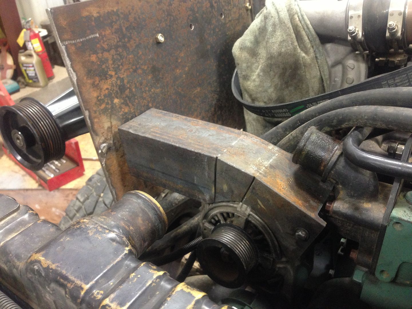
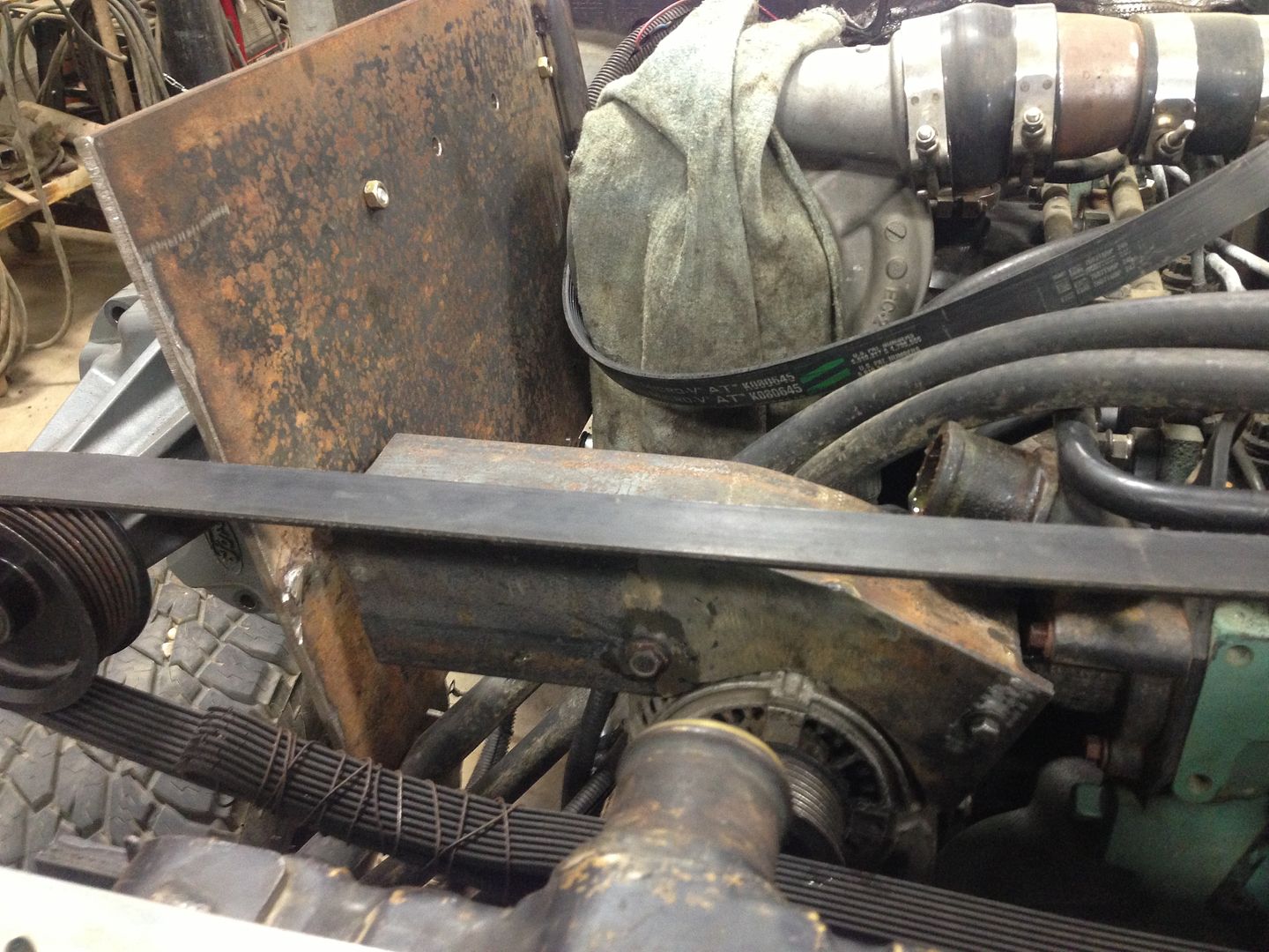
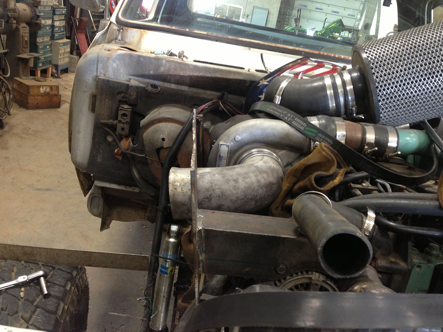
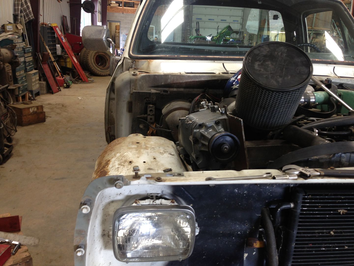
According to the math I've attempted it'll be marginal, but my math is based off of equations that I'm not sure I'm using correctly. Since I'm back at the house now, beer in hand and probably not putting on pants for the rest of the night, I'll run them past you all and see what you think. My front mount turned out really well, but I cut my back one off and have yet to be happy with anything else I've tacked in there.


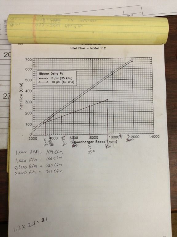
So, here's what my math got me, it's my engine's expected air consumption compared to the blower's output at comparable RPM. You can see that the blower outpaces it pretty well up top, but down low it almost seems to become a restriction. I used the CIDxRPMxVE, but I plugged different RPMs in to get my lower numbers instead of just the max expected. Dunno if it works, but it's what I did.


37A87B39-3BB8-473E-B958-229696CB26DC-915-0000008015A2E134_zps39800ead.jpg


Does the lower end of that line not mean anything because of how it was calculated?
 
One of the nice things about the positive displacement style SCs is the ability to calculate output in direct proportion to rpm.
Just remember the SC is 122ci per rev and your engine is 359ci every other rev. so the SC is moving 244ci when running the same speed as the crank.
You have the SC turning 3x crank speed, so it is moving 732ci (at 100%ve) per every 359ci (at 100%ve) of the engine.
 
Strangely, I actually understand that.
Especially since I realize that 've' refers to Volumetric Efficiency.

So, at what RPM (at the SC snout) does the efficiency of the SC go down and does it have any relation to inlet and outlet sizing?
Also, I would assume there IS a max RPM limit (at the SC snout) before all hell breaks loose?

Mark.
 
Oh man, I think I calculated mine as a 2 stroke, didn't I? :doh:

That's good to know though, better to have to take some out then have to try to build more in. :lolly:
 
So, at what RPM (at the SC snout) does the efficiency of the SC go down and does it have any relation to inlet and outlet sizing?
Also, I would assume there IS a max RPM limit (at the SC snout) before all hell breaks loose?

Mark.

that is specific to each SC.
 
That's gonna be the shortest silicone coupler in the world. LOL

Thinking of chucking it up, hitting it with the torch, and making a bell mouth inside the mount. Is this a waste of time? I doubt it'll be a perfect radius through the entire thing but I can keep it concentric on the lathe. Should I just hack it off and burn it in, making it easier to ensure no leaks?

AAB696D7-CFA9-40BD-A05E-06FFB4A9E603-2396-0000026C73A4A735_zps39e7bce2.jpg


Lost an inch of two in the brace-making, looks like the inner fender will be receiving a complimentary massage.

0EF0D819-D0C4-449C-A295-EA4D9C6866AE-2396-0000026C790BEA32_zpsf396d14f.jpg


Through hood filter so I can get it out of our shop tonight. Do I have to be in the oraler thread? :lolly:
 
Been a while since I EAGERLY awaited progress on a thread!
C'mon man, let's light this thing up! :evil

Mark.
 
Last edited:
Back
Top